
Sensor signal conditioner

a transducer and signal conditioner technology, applied in the direction of instruments, liquid/fluent solid measurement, code conversion, etc., can solve the problems of affecting the output signal of the transducer, not being very accurate in analog approaches, and not being typically the case, etc., to achieve the effect of extensive hardware and software setup

Inactive Publication Date: 2006-02-07
ADVANCED CUSTOM SENSORS
View PDF14 Cites 11 Cited by
  • Summary
  • Abstract
  • Description
  • Claims
  • Application Information

AI Technical Summary

Benefits of technology

[0022]The present invention provides temperature compensation, linearization and amplification of the output of a transducer for which setting trim values avoids extensive hardware and software setup. The present invention also provides trim value set up to temperature compensate, linearize and amplify the output of transducers, which can be performed simultaneously on many transducers despite differences between individual components.

Problems solved by technology

Although linearity of the transducer output signal is desirable, it is typically not the case.
In addition to imperfections in sensor element manufacturing, the conditioning circuit itself may contribute to non-linearity of the transducer output signal.
Temperature, both ambient temperature and temperature changes caused by power dissipation in the circuit and sensor, may also affect the transducer output signal.
The analog approach is not very accurate, however, due to the repeatability of thermistors and limited selection in resistor values.
Also, the analog approach is very time consuming since it requires several iterations in resistor installation and temperature test.
The calibration set up is very expensive since, for example, it may have to accommodate two-way digital communication between the IC chip and a computer and, also, analog data transmission of multiple sensors.
Despite the advantages of using ASIC chips for temperature compensation, linearization and amplification of transducer output, including better sensing accuracy, the current practice does not take full advantage of the cost-saving features of the digital approach because of the extensive hardware and software setup involved in adjusting the output and setting trim values as described above.
Such communication setup may be complicated and time-consuming, adversely affecting some of the advantages of mass production, such as time and cost efficiency.

Method used


Image

  • Sensor signal conditioner
  • Sensor signal conditioner
  • Sensor signal conditioner

Examples


Embodiment Construction

[0032]The following detailed description is of the best currently contemplated modes of carrying out the invention. The description is not to be taken in a limiting sense, but is made merely for the purpose of illustrating the general principles of the invention, since the scope of the invention is best defined by the appended claims.

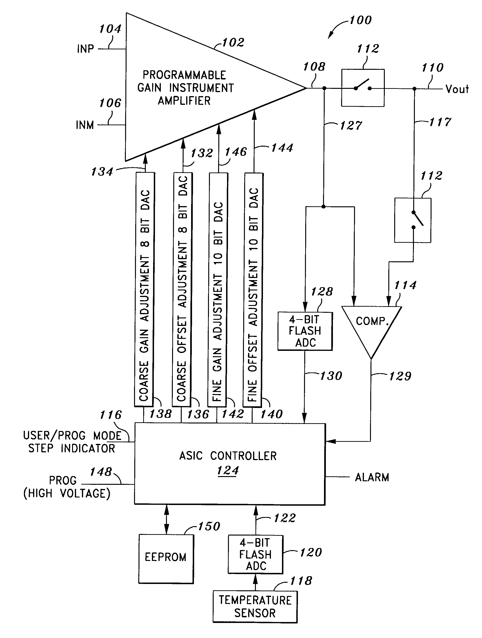
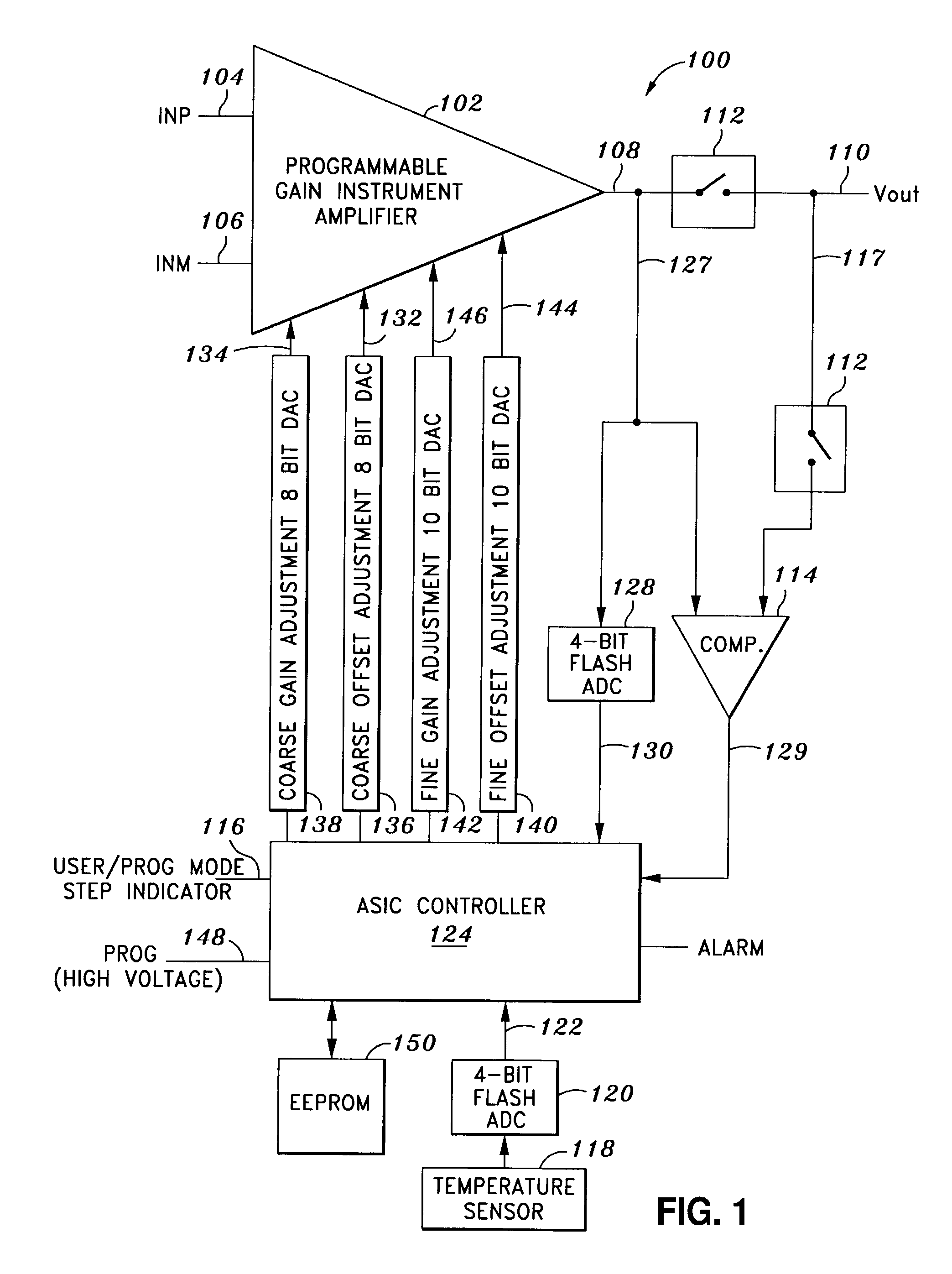
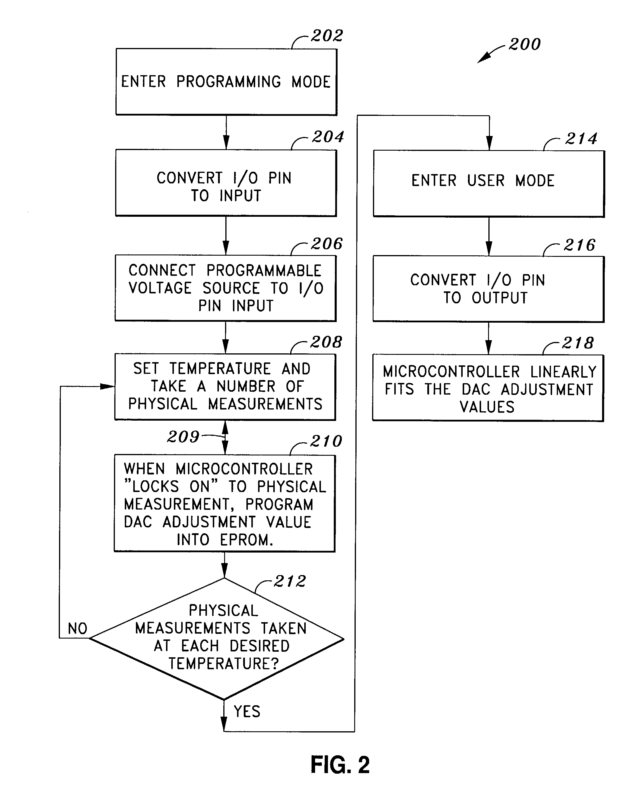
[0033]The present invention provides temperature compensation, linearization, and amplification of the output of a sensor for electronic instrumentation for which setting trim values for the temperature compensation, linearization, and amplification circuit can be performed without extensive hardware and software setup. The present invention also provides a signal conditioning circuit for temperature compensation, linearization, and amplification of the signal output of sensors or transducers in which, in contrast to the prior art, certain aspects of the decision making for trim value set up can be taken over by the signal conditioning circuit itself, r...


PUM


Abstract

A sensor signal conditioner for temperature compensating, linearizing, and amplifying sensor signal output in electronic instrumentation circuits includes a programmable gain instrument amplifier having an input connected to a sensor; and a comparator for comparing an output voltage of the amplifier to a desired output voltage value. A micro-controller controls the instrument amplifier gain and offset. A mode switch converts an I / O pin to input the desired output voltage value in programming mode and connects the I / O pin to the amplifier output in user mode. A memory stores a programming protocol in the sensor signal conditioner so that in programming mode, the protocol stores programmed values and linearly fits the programmed values to set trim values for temperature compensating, linearizing, and amplifying the instrument amplifier output. The I / O pins and mode switches of several sensor signal conditioners can be controlled simultaneously to mass produce transducers using the sensor signal conditioner.

Description

BACKGROUND OF THE INVENTION[0001]The present invention generally relates to sensors for electronic instrumentation and, more particularly, to temperature compensation, linearization, and amplification of the output signal of a transducer.[0002]Transducers are used in a wide variety of engineering applications to convert various physical quantities to an electrical signal. An example of one type of such a transducer is the pressure transducer, which usually includes a pressure sensor and some associated circuitry for producing an electrical output. Pressure transducers may be used for applications as varied as sensing oil pressure in an engine to sensing cabin air pressure in an aircraft. A pressure transducer typically provides an output voltage or current that is a function of pressure applied to the sensor. For example, the output voltage or current may be some specific value at zero pressure and may increase in proportion to the increase in pressure on the sensor. In such a case,...

Claims


Application Information

Patent Timeline
IPC IPC(8): G06F19/00G01D3/02G01D18/00G01L19/02G01L19/04
CPCG01D18/008G01L9/025G01D3/022
Inventor CHU, CHARLESYOUNG, MICHAEL
Owner ADVANCED CUSTOM SENSORS
Learn More