Automatic measurement of fuel cell resistance

a technology of automatic measurement and fuel cell, applied in the field of fuel cells, can solve the problems of high cost of fuel processing, high power consumption, and tendency of the catalyzed membrane to dry out, and achieve the effect of increasing the resistan

Inactive Publication Date: 2005-05-05
MTI MICROFUEL CELLS
View PDF17 Cites 17 Cited by
  • Summary
  • Abstract
  • Description
  • Claims
  • Application Information

AI Technical Summary

Benefits of technology

[0021] The limitations of prior techniques have been overcome by the present invention, which provides a unique method and apparatus for measuring the resistance of a direct oxidation fuel cell system. As used herein, a direct oxidation fuel cell system shall include a direct oxidation fuel cell stack, a direct oxidation fuel cell array, and/or an individual direct oxidation fuel cell. Accordingly, although the illustrative embodiment of the invention is described with reference to a fuel cell stack, the invention is not limited thereto, but it is readily adaptable for use with an individual fuel cell and/or a fuel cell array. Thus, the word “stack,” as used herein shall include an individual fuel cell and a fuel cell array, and the invention equally applies to an array or an individual fuel cell. Furthermore, the illustrative embodiment is also described with reference to a “direct oxidation fuel cell,” such as a direct methanol fuel cell (DMFC), however, it should also be understood that the invention is equally applicable to other types of fuel cells, such as hydrogen fuel cells.
[0022] In accordance with the invention, the load on the fuel cell stack is varied, and the resultant changes in stack voltage, and current, allow a calculation of fuel cell resistance. More specifically, the initial stack voltage, and stack current are read. Then, the stack load is varied, and a new stack current and stack voltage are immediately measured. From these measurements, one can readily solve for the stack resistance, which provides an indication of cell hydration. As noted, as resistance increases, ther

Problems solved by technology

However, because fuel processing is expensive and generally requires expensive components, which occupy significant volume, reformer based systems are presently limited to comparatively large, high power applications.
For example, particularly in a vapor fed cell, there is a tendency for the catalyzed membrane to dry out during operation, or when the fuel cell is shut down.
Further, when the fuel cell is not in operation, the membrane of a microfuel cell system may become dehydrated due, at least in part, to the lack of water generation at the cathode.
This also undesirable particularly in situations when the fuel cell is in a standby status, such as when the fuel cell system is employed in a hybrid power source that contains the fuel cell and a battery.
During this time period, cell dehydration can occur, an

Method used


Image

  • Automatic measurement of fuel cell resistance
  • Automatic measurement of fuel cell resistance
  • Automatic measurement of fuel cell resistance

Examples


Embodiment Construction

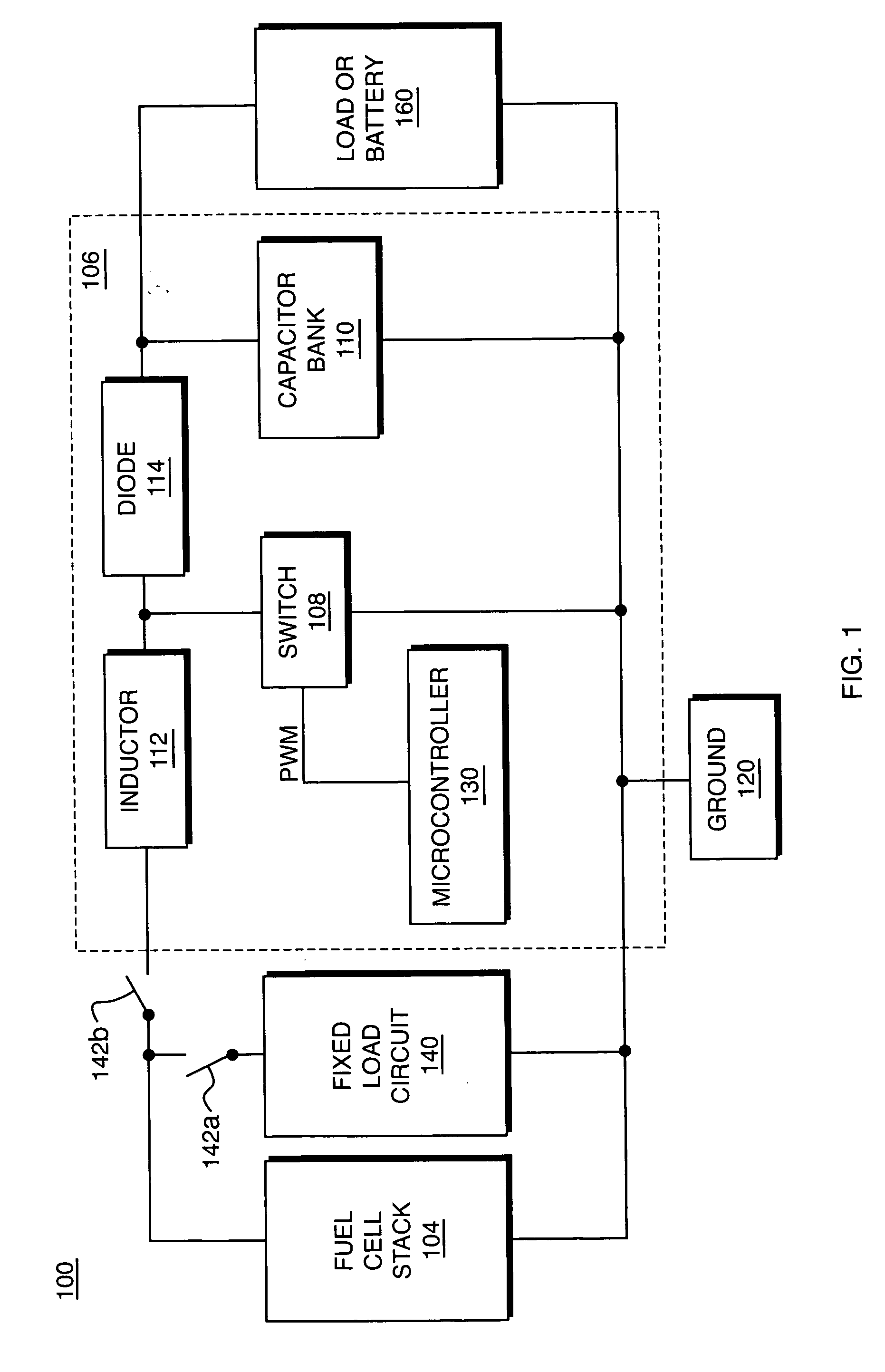
[0032]FIG. 1 schematically illustrates a system 100 for controlling a fuel cell system, which in the illustrative embodiment is a fuel cell stack 104. A switching DC-DC converter circuit illustrated within dashed box 106 is employed to control certain aspects of the operation of the fuel cell stack 104.

[0033] By way of background, the DC-DC converter circuit 106 operates in a boost configuration in the following manner. In a basic boost configuration, if the switch 108 (typically comprised of a set of switches) has been open for a long time, the voltage across the capacitor bank 110 is equal to the input voltage from the fuel cell stack 104. During a charge phase, when the switch 108 closes, the input voltage is impressed across the inductor 112. The diode 114 prevents the capacitor bank 110 from discharging to ground 120, because the input voltage is DC, current through the inductor 112 rises linearly with time at a rate that is proportional to the input voltage divided by the ind...


PUM

PropertyMeasurementUnit
Electrical resistanceaaaaaaaaaa
Electric potential / voltageaaaaaaaaaa

Abstract

This invention presents a method and apparatus for measuring the resistance across a fuel cell stack, a fuel cell array, or an individual fuel cell. The invention employs a fixed load circuit to switch a fixed resistance or to connect a fixed load current to the stack or array. When the load is turned on, the stack voltage is read, then the load is turned off and the stack voltage is read again to determine the voltage jump. A change in resistance is calculated that is related to cell hydration. In accordance with another aspect of the invention, the stack includes a programmable DC-DC switch under PWM microprocessor control. The DC-DC converter is used to switch the load on and off and the voltage jump is read using a sample and hold methodology with an optional instrumentation amplifier and a Kalman filter to determine accurate results for resistance with no additional hardware. The resistance measurements are used to identify and evaluate cell hydration.

Description

BACKGROUND OF THE INVENTION [0001] 1. Field of the Invention [0002] The present invention relates generally to fuel cells and, more specifically, to measuring certain operating characteristics of such fuel cells, fuel cell stacks and fuel cell arrays. [0003] 2. Background Information [0004] Fuel cells are devices in which an electrochemical reaction is used to generate electricity. A variety of materials may be suited for use as a fuel depending upon the materials chosen for the components of the cell. Organic materials, such as methanol or natural gas, are attractive fuel choices due to the their high specific energy. [0005] Fuel cell systems may be divided into “reformer-based” systems (i.e., those in which the fuel is processed in some fashion to extract hydrogen from the fuel before it is introduced into the fuel cell system) or “direct oxidation” systems in which the fuel is fed directly into the cell without the need for separate internal or external processing. Most currently...

Claims


Application Information

Patent Timeline
IPC IPC(8): H01M8/04
CPCH01M8/04291H01M8/04492H01M8/04559Y02E60/50H01M8/04649H01M8/04925H01M8/1011H01M8/04589
Inventor LECKY, JOHN EDWARD
Owner MTI MICROFUEL CELLS
Why Eureka
Try Eureka