Packing container and method of manufacturing the containers

a packaging container and manufacturing method technology, applied in the field of packaging containers, can solve the problems of increasing the cost reducing the quality of the packaging container, and complicated structure of the packaging container manufacturing apparatus, so as to simplify the process of fabricating the packaging container. , the effect of pleasing sensation

Inactive Publication Date: 2006-02-14
TETRA LAVAL HLDG & FINANCE SA
View PDF19 Cites 2 Cited by
  • Summary
  • Abstract
  • Description
  • Claims
  • Application Information

AI Technical Summary

Benefits of technology

[0017]Therefore, there is eliminated the necessity of stopping the container body on the conveyer or temporarily removing the container body from the conveyer and returning it onto the conveyer after attachment of the cap. Accordingly, variation in the position at which the cap is attached is prevented, so that the quality of the packaging container can be improved. In addition, the structure of the packaging container manufacturing apparatus can be simplified, and the cost of the packaging container manufacturing apparatus can be lowered.
[0024]In this case, since the thick portion is present around the discharge opening portion, the drinker obtains a pleasant sensation upon placement of his / her lips on portions around the discharge opening portion. In addition, drinking the liquid food is easy, and does not require use of a straw.
[0025]Further, since the thick portion is formed integrally with the lip, the process of fabricating the packaging container can be simplified.
[0032]Therefore, there is eliminated the necessity of stopping the container body on the conveyer or temporarily removing the container body from the conveyer and returning it onto the conveyer after attachment of the cap. Accordingly, variation in the position at which the cap is attached is prevented, so that the quality of the packaging container can be improved. In addition, the structure of the packaging container manufacturing apparatus can be simplified, and the cost of the packaging container manufacturing apparatus can be lowered.

Problems solved by technology

Therefore, the position at which the cap is attached varies, resulting in a decrease in quality of the packaging container.
Any attempt to eliminate such variation in the cap attachment position makes the structure of the packaging container manufacturing apparatus complicated and increases the cost of the packaging container manufacturing apparatus.
The pull-tab-type packaging container has a drawback in that when a drinker places his / her lips on the discharge opening 221 in an opened state to thereby drink liquid food directly from the discharge opening 221, the drinker receives an unpleasant sensation from portions around the discharge opening 221.

Method used


Image

  • Packing container and method of manufacturing the containers
  • Packing container and method of manufacturing the containers
  • Packing container and method of manufacturing the containers

Examples


first embodiment

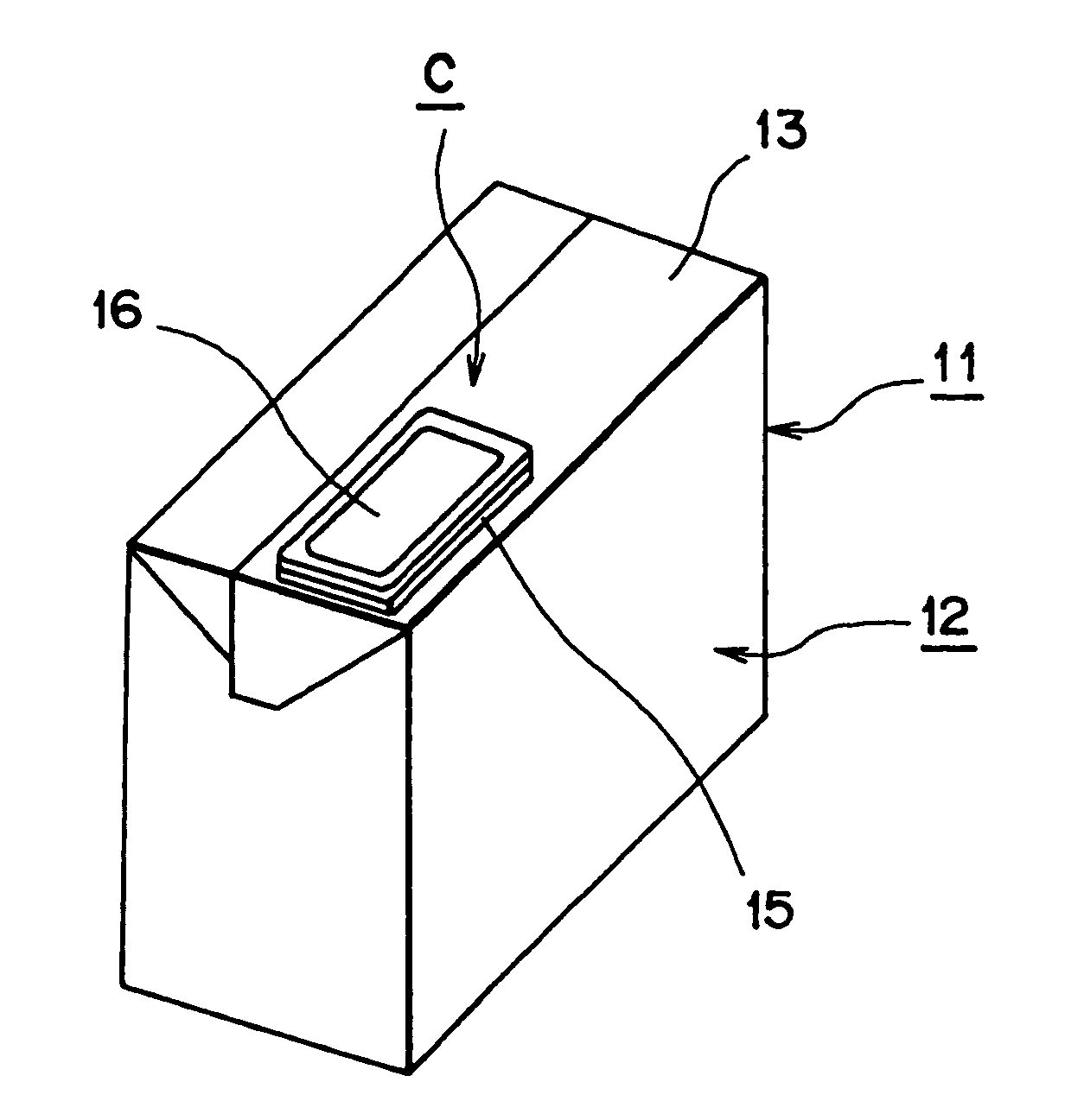
[0085]FIG. 2 is a perspective view of a packaging container according to the present invention.

[0086]In FIG. 2, reference numeral 11 denotes a packaging container which comprises a container body 12 formed from a packaging material and a cap unit C. Reference numeral 13 denotes a top wall of the container body 12, and the cap unit C is attached to a cap attachment portion of the top wall 13 by any of various application methods such as a hot melt method, a heat sealing method, or an ultrasonic sealing method. It is to be noted that an unillustrated punched hole is formed at the cap attachment portion of the top wall 13.

[0087]The cap unit C consists of an unillustrated base paper sheet; a collar portion 15 fixed to the top wall 13 via the base paper sheet; a lid portion 16; an unillustrated pull tab, and an unillustrated inner tape. The lid portion 16 is removably fitted into the collar portion 15 via the pull tab. The pull tab covers the punched hole and is welded to the collar port...

second embodiment

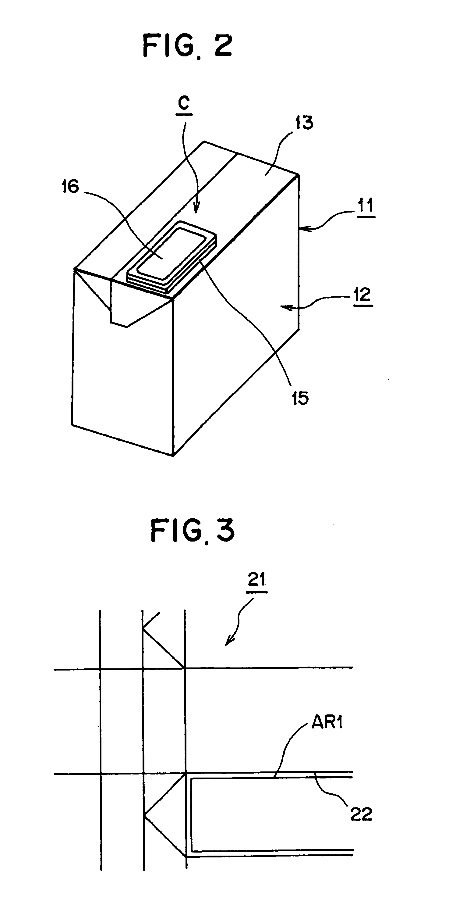
[0108]FIG. 14 is a view showing a method of manufacturing a packaging container according to the present invention.

[0109]In a first step, the packaging material 21 is transported along an unillustrated packaging material transport path by means of an unillustrated conveyer serving as a packaging material transport apparatus, and is fed to a cap attachment station defined at a predetermined position on the packaging material transport path. In a second step, the cap 14 is attached to the packaging material 21 by means of a cap applicator disposed at the cap attachment station.

[0110]In this case, a sheet that does not include an aluminum layer is used as a base sheet, and the base sheet is removed from the cap 14 before the cap 14 is attached to the packaging material 21. A seal tape 35 is used for attachment. The seal tape 35 has a three-layer structure in which a polyethylene resin layer is coated on either side of an aluminum layer.

[0111]When the cap sheet 25 (see FIG. 7) is fed to...

fifth embodiment

[0133]Next, the present invention will be described.

[0134]FIG. 24 is a view showing an initial state of a packaging container according to the fifth embodiment of the present invention; and FIG. 25 is a view showing an opened state of the packaging container according to the fifth embodiment of the present invention.

[0135]In FIGS. 24 and 25, reference numeral 229 denotes a packaging container; and 230 denotes a container body. The container body 230 has a body portion 231 having a substantially octagonal cross section, an upper end portion 232 which extends upward from the body portion 231 and has a substantially octagonal cross section at its lower end and a substantially rectangular cross section at its upper end, and an unillustrated lower portion which extends downward from the body portion 231 and has a substantially octagonal cross section at its upper end and a substantially rectangular cross section at its lower end. The body portion 231 is formed by a front wall 234, an uni...


PUM

PropertyMeasurementUnit
areaaaaaaaaaaa
surface areaaaaaaaaaaa
shapeaaaaaaaaaa

Abstract

The packaging container includes a container body formed from a packaging material, and a cap unit attached to a top wall of the container body. The cap unit includes a lip, a pull tab which covers a discharge opening and an inner tape which covers the discharge opening portion from a reverse side of the packaging material. Since the cap is attached to the packaging material in advance of forming the container, positioning of the container body is not required for cap attachment.

Description

CROSS-REFERENCE TO RELATED APPLICATIONS[0001]This application is a National Phase Application (35 USC 371) of PCT / JP00 / 00845 and claims priority of Japanese Application No. 11-38741 filed Feb. 17, 1999 and Japanese Application No. 11-312529 filed Nov. 2, 1999.TECHNICAL FIELD[0002]The present invention relates to a packaging container and to a method of manufacturing the same.BACKGROUND ART[0003]Conventionally, liquid food such as milk or soft drink is sold in a form such that the liquid food is contained in a brick-shaped or polyhedral packaging container formed of a packaging material. In order to enable portionwise discharge of liquid food, there is provided a cap-type packaging container whose container body has a cap that can be opened and closed freely.[0004]In this case, a packaging container manufacturing apparatus is designed to include a charging machine and a cap applicator. In the charging machine, a packaging material is formed into a container body, and a liquid food is...

Claims


Application Information

Patent Timeline
Patent Type & Authority Patents(United States)
IPC IPC(8): B65B61/18B31B1/90B65D5/72B65D5/74B65D6/40B65D17/50B65D77/28
CPCB31B1/90B65D5/727B65D5/749B65D77/28B65D17/505B31B2201/90Y10S493/962B65D2517/5008B65D2517/5089B31B50/81B31B50/85B65D5/74
Inventor BERGERIOUX, CLAUDEMORIYAMA, YASUYUKI
Owner TETRA LAVAL HLDG & FINANCE SA
Why Eureka
Try Eureka