Temperature compensated time-of-flight mass spectrometer

a mass spectrometer and time-of-flight technology, applied in mass spectrometers, separation of dispersed particles, separation processes, etc., can solve the problems of reduced resolution, increased complexity in the control system and software required, and competition for ionization with sample molecules

Active Publication Date: 2006-02-14
THERMO FINNIGAN
View PDF7 Cites 30 Cited by
  • Summary
  • Abstract
  • Description
  • Claims
  • Application Information

AI Technical Summary

Benefits of technology

[0015]In general, the invention provides apparatus and methods for compensating for temperature variations in a time-of-flight mass spectrometer. The time-of-flight mass spectrometer comprises material that have different thermal expansion coefficients, the materials being combined in such a way that the length of the ion drift region is variant, and self adjusting with temperature. The adjustment is such as to compensate for the length changes resulting from thermal expansion or contraction in the ion optical elements, such that ions of substantially equivalent mass to charge ratios maintain a constant flight time from one location to another through the system. This allows for use of standard construction methods for the ion optical elements.

Problems solved by technology

It has been observed that ions of a particular mass to charge ratio typically reach the detector with a range of arrival times. The range of arrival times can be due to effects of location in the extraction field at the output of the ion source, and the initial kinetic energy, which ultimately results in reduced resolution.
The disadvantage of this is that there may be interference of the standard in the mass spectrum when unknown samples are being analyzed, and there is competition for ionization with the sample molecules, unless ionized in a separate source.
These methods typically require very accurate measurement of the temperature, and that adds additional costs and complexity in the control system and software required.
Once again, this adds additional costs and complexity to the instrument.
However it is not currently practical to build an entire structure out of such materials.
A compromise is to build combinations of construction material with different thermal expansion coefficients, such that the effects of their thermal expansions compensate for each other, and the lengths of the various ion and / or optical elements remain constant, but this can mean complex construction.
Since most TOFMSs are relatively large instruments, implementation of this method adds considerably cost to the instrument.

Method used


Image

  • Temperature compensated time-of-flight mass spectrometer
  • Temperature compensated time-of-flight mass spectrometer
  • Temperature compensated time-of-flight mass spectrometer

Examples


Embodiment Construction

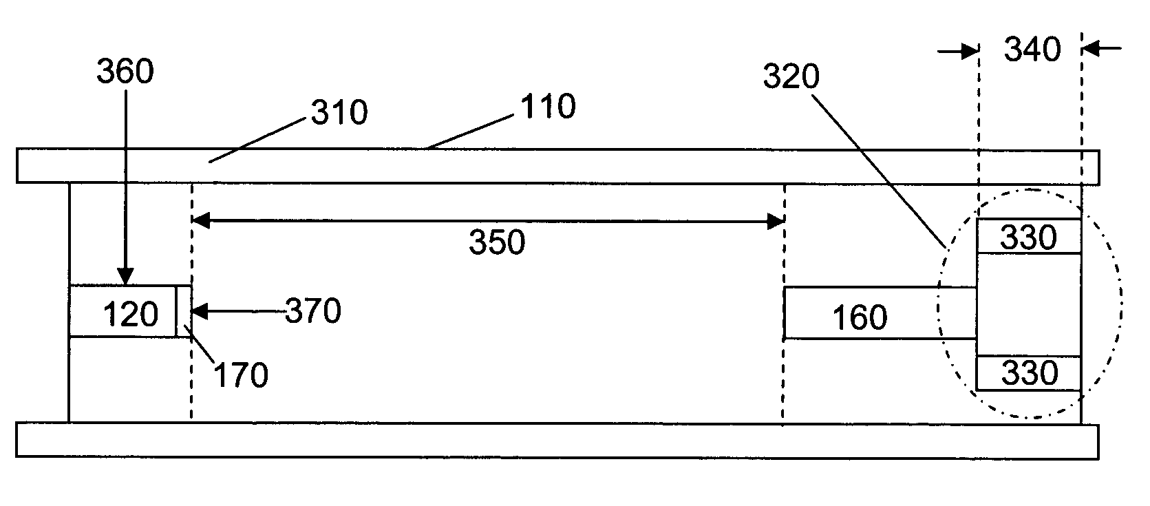
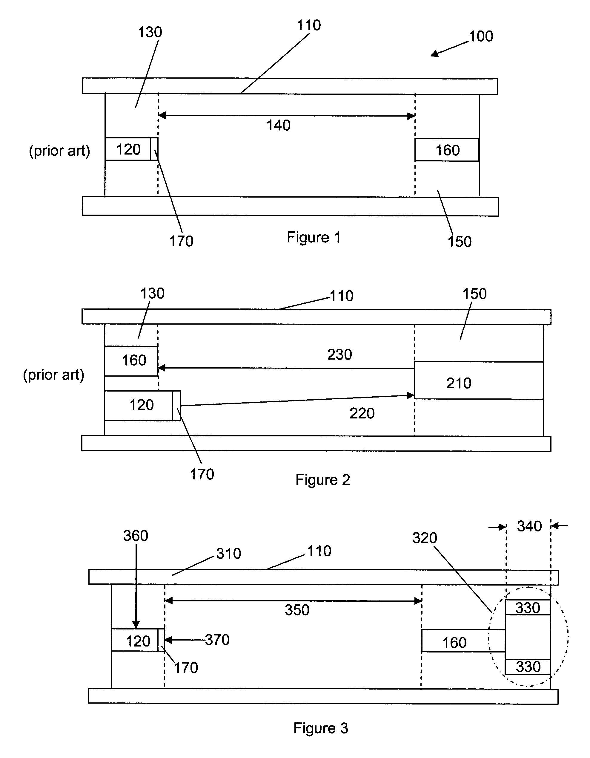
[0030]FIG. 1 shows, in schematic terms, a prior art linear time-of flight mass spectrometer (TOFMS) 100. The ions created for use in a TOFMS can be created in a “pulsed” form, created in a very short time interval (several ns) or can be accumulated for a certain time interval (typically in the μs range), and then ejected or extracted into the TOFMS by a voltage pulse with a fast rise time. The ions can be formed inside the time-of-flight chamber 110 or formed outside the chamber with the ions then being transported into the time-of-flight chamber 110. The TOF comprises a source of ions 120 such as an electrospray ion source, an electron impact ion sours, a chemical ionization source, an APCI or MALDI source (which generate ions from material received from, for example a liquid chromatograph). An orthogonal drift region as opposed to a linear drift region (as shown) can be employed if so desired.

[0031]Ionic particles from the source of ions 120 which may be housed in the source regio...


PUM


Abstract

An apparatus that comprises material which have different thermal expansion coefficients, combined in such a way that the length of the drift region is variant, and self adjusting with temperature. The adjustment is such as to compensate for the length changes resulting from thermal expansion or contraction in other ion optical elements, such that ions of substantially equivalent mass to charge ratios maintain a constant flight time though the system. This allows for use of standard construction methods for the ion optical elements.

Description

BRIEF DESCRIPTION OF THE INVENTION[0001]The invention relates to time-of-flight mass spectrometers and more particularly to a method and apparatus for compensating for temperature variations in the mass spectrometer.BACKGROUND OF THE INVENTION[0002]Time-of-flight mass spectrometry (TOFMS) is based upon the principle that ions of different mass to charge ratios travel at different velocities such that a packet of ions accelerated to a specific kinetic energy separates out over a defined distance according to the mass to charge ratio. By detecting the time of arrival of ions at the end of the defined distance, a mass spectrum can be built up.[0003]Orthogonal TOFMSs operate in so-called cyclic mode, in which successive packets of ions are accelerated to a kinetic energy, separated in flight according to their mass to charge ratios, and then detected. The complete time spectrum in each cycle is detected and the results added to a histogram.[0004]It has been observed that ions of a parti...

Claims


Application Information

Patent Timeline
Patent Type & Authority Patents(United States)
IPC IPC(8): H01J49/40
CPCH01J49/40
Inventor DAVIS, STEPHEN C.EARLEY, LEEHARDMAN, MARKLAND, ADRIANPERELMAN, GERSHON
Owner THERMO FINNIGAN
Why Eureka
Try Eureka