
Semiconductor device saving data in non-volatile manner during standby

a technology of semiconductor devices and data, applied in the field of semiconductor devices, can solve the problems of data loss, data of flip-flops within logic circuits or volatile memory, and increase in leak current between source and drain of transistors in off-state, so as to achieve rapid data saving, data can be saved, and current consumption during standby is reduced

Inactive Publication Date: 2006-02-14
RENESAS TECH CORP
View PDF10 Cites 41 Cited by
  • Summary
  • Abstract
  • Description
  • Claims
  • Application Information

AI Technical Summary

Benefits of technology

Enables rapid data saving without interrupting normal operations and efficiently reduces current consumption during standby by utilizing a thin film magnetic memory cell in conjunction with a volatile latch circuit, allowing for quick data transfer and storage.

Problems solved by technology

With such a thinner gate oxide film, a gate leak current further increases.
Reduction of the gate length also causes an increase in a leak current between source and drain of the transistor in an off-state.
When the power supply voltage is turned off, however, data of a flip-flop within a logic circuit or a volatile memory will be lost.
Because of this very long time period, much processing time is required before the power supply voltage is turned off.
As a result, a transition time to a standby mode for reducing current consumption will be late.
In addition, as the flash EEPROM also takes a relatively long time to read data, a long time period is needed to read data and return the data of the volatile memory or flip-flop to its original state after the power is reset.
Thus, it also takes a long time to activate the device.
Further, it is uneconomical to provide a memory for temporary saving on an external printed-circuit board, because the number of elements in the whole system as well as an area of the external printed-circuit board increase.

Method used


Image

  • Semiconductor device saving data in non-volatile manner during standby
  • Semiconductor device saving data in non-volatile manner during standby
  • Semiconductor device saving data in non-volatile manner during standby

Examples


first embodiment

[0040][First Embodiment]

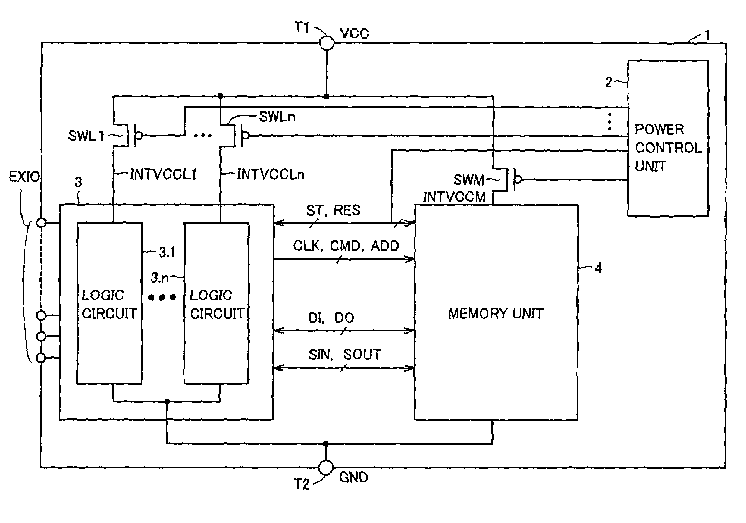
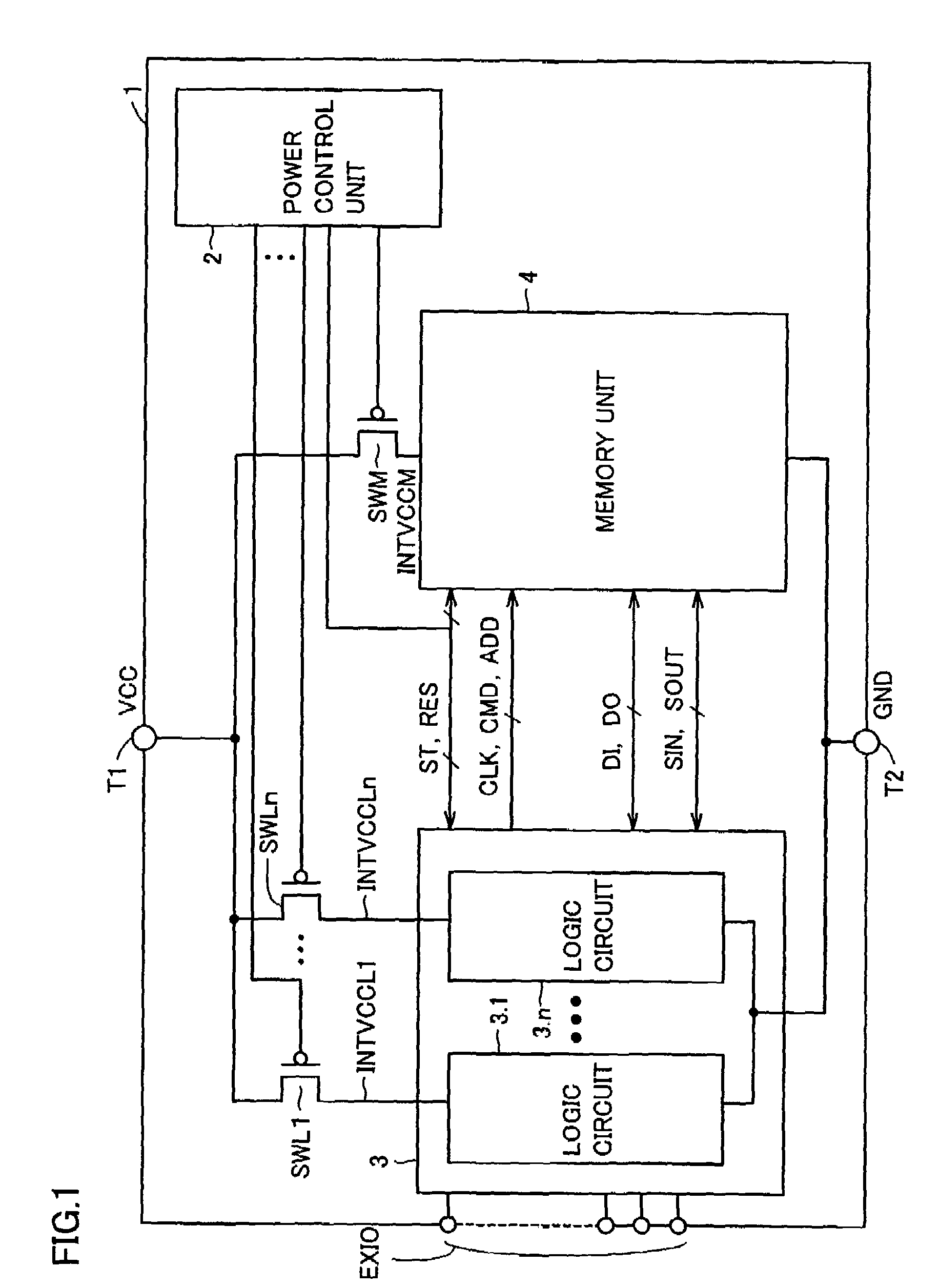
[0041]FIG. 1 is a schematic block diagram of a whole structure relating to a power control operation of a semiconductor device 1 of a first embodiment 1 according to the present invention.

[0042]Referring to FIG. 1, semiconductor device 1 includes a power supply terminal T1 receiving a power supply potential VCC fed from the outside, a ground terminal T2 receiving a ground potential GND fed from the outside, and a terminal EXIO for communicating signals with the outside.

[0043]Semiconductor device 1 further includes a logic unit 3, a memory unit 4, switch circuits SWL1–SWLn and SWM, and a power control unit 2.

[0044]Logic unit 3 includes logic circuits 3.1–3.n . As will be described below, logic circuits 3.1–3.n include a circuit such as a flip-flop for temporarily storing data and a combinational circuit such as an AND circuit.

[0045]Power control unit 2 performs on / off controls of switch circuits SWL1–SWLn and SWM, and also outputs control signals ST, RES to lo...

second embodiment

[0127][Second Embodiment]

[0128]A system LSI is formed with a plurality of circuit blocks, and a degree of integration thereof is increasing in recent years as a transistor becomes smaller. On the other hand, a decrease in a transistor threshold voltage due to a decrease in an operation voltage causes an increased leak current of the transistor. In addition, as a gate oxide film of the transistor becomes thinner, a leak current of the gate oxide film increases. Furthermore, a parasitic PN diode is formed between a source / drain and a substrate of the transistor. A reverse bias is usually applied to the PN diode. As the size thereof is reduced, a concentration of an impurity of the source / drain of the transistor increases, and a leak current of the PN diode at the application of reverse bias increases.

[0129]The three problems of the leak current described above result in an increased current during standby for the whole system LSI. In a second embodiment; another structure to decrease ...


PUM


Abstract

A power control unit activates a control signal ST for a circuit block to be set to a standby state before turning off power of the circuit block or a whole chip, and saves an operation result of data processing of the circuit block into a memory unit. When the power is again supplied to the circuit block in the standby state, the power control unit activates a control signal RES after the power supply is started and restores the data saved in the memory unit to the circuit block. Flip-flops in the circuit block are connected in series when the saving or restoring of data is performed, and perform a data transfer operation with a path different from that in a normal operation. Therefore, a semiconductor device can be provided which can rapidly transit to a standby mode having reduced current consumption while holding internal information.

Description

RELATED APPLICATION[0001]This application is a divisional of U.S. patent application Ser. No. 10 / 390,027, filed Mar. 18, 2003, now U.S. Pat. No. 6,914,845 which claims priority of Japanese application 2002-295130(P), filed Oct. 8, 2002, and the contents of which are hereby incorporated by reference.BACKGROUND OF THE INVENTION[0002]1. Field of the Invention[0003]The present invention relates to a semiconductor device and, more specifically, to a semiconductor device which can save processed data in an integrated thin film magnetic memory element when power is turned off.[0004]2. Description of the Background Art[0005]In recent years, large-scale circuits can be integrated in a semiconductor device, and a system LSI (large-scale integrated circuit), in which a logic circuit and a bulk memory is integrated on one chip, has been developed. In such a system LSI, a logic circuit unit and a memory unit transmit and receive information such as address, command and data via a prescribed port...

Claims


Application Information

Patent Timeline
Patent Type & Authority Patents(United States)
IPC IPC(8): G11C11/14G11C14/00G11C11/15
CPCG11C14/0081
Inventor OOISHI, TSUKASA
Owner RENESAS TECH CORP
Learn More