Method for manufacturing a wire stent coated with a biocompatible fluoropolymer

Inactive Publication Date: 2006-02-21
VASCULAR CONCEPTS HLDG
View PDF130 Cites 30 Cited by
  • Summary
  • Abstract
  • Description
  • Claims
  • Application Information

AI Technical Summary

Benefits of technology

[0006]The process of this invention is achieved by pretreating a spool of wire to achieve a predetermined shape to the wire and returning the treated wire to its spool. The wire is then fed into an ePTFE extrusion machine where the wire feed is regulated depending on the speed of the extrusion machine. The wire is fed first into a nozzle of the extruder, the nozzle having a concent

Problems solved by technology

None of these prior art disclosures teach how to coat a wire used in a prosthe

Method used


Image

  • Method for manufacturing a wire stent coated with a biocompatible fluoropolymer
  • Method for manufacturing a wire stent coated with a biocompatible fluoropolymer
  • Method for manufacturing a wire stent coated with a biocompatible fluoropolymer

Examples


Example

[0016]Throughout the following detailed description, the same reference numerals refer to the same element in all figures.

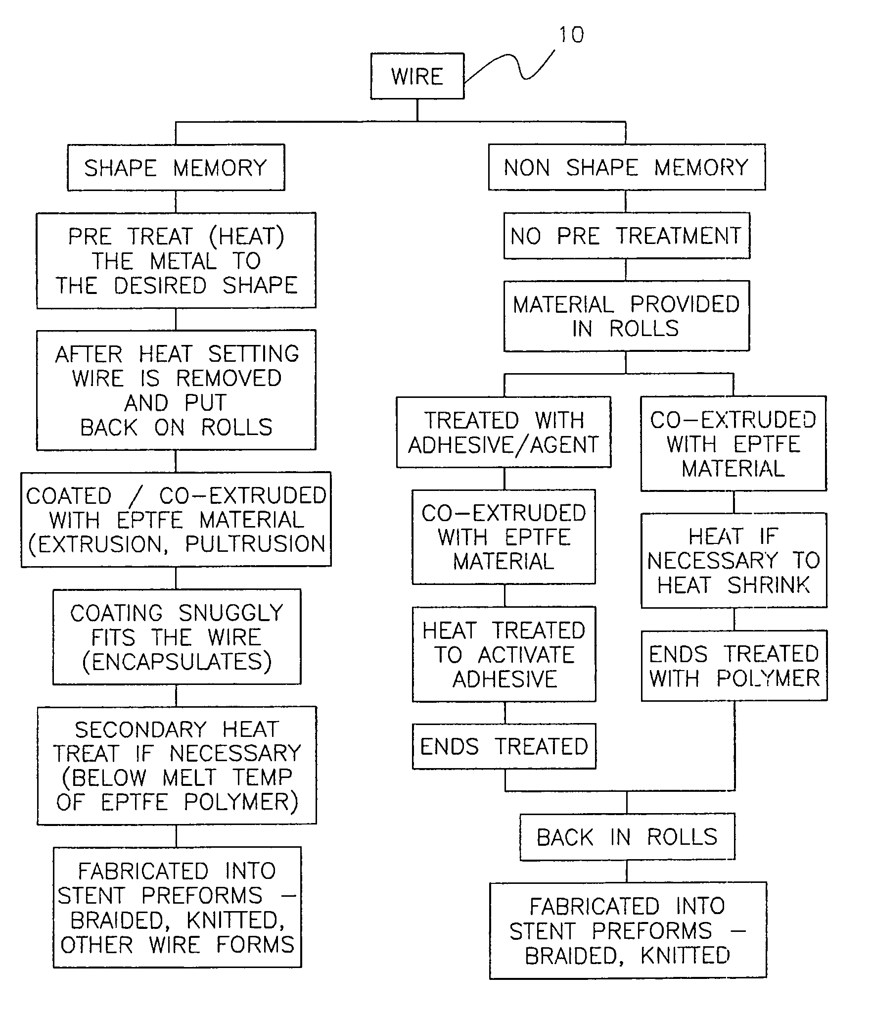
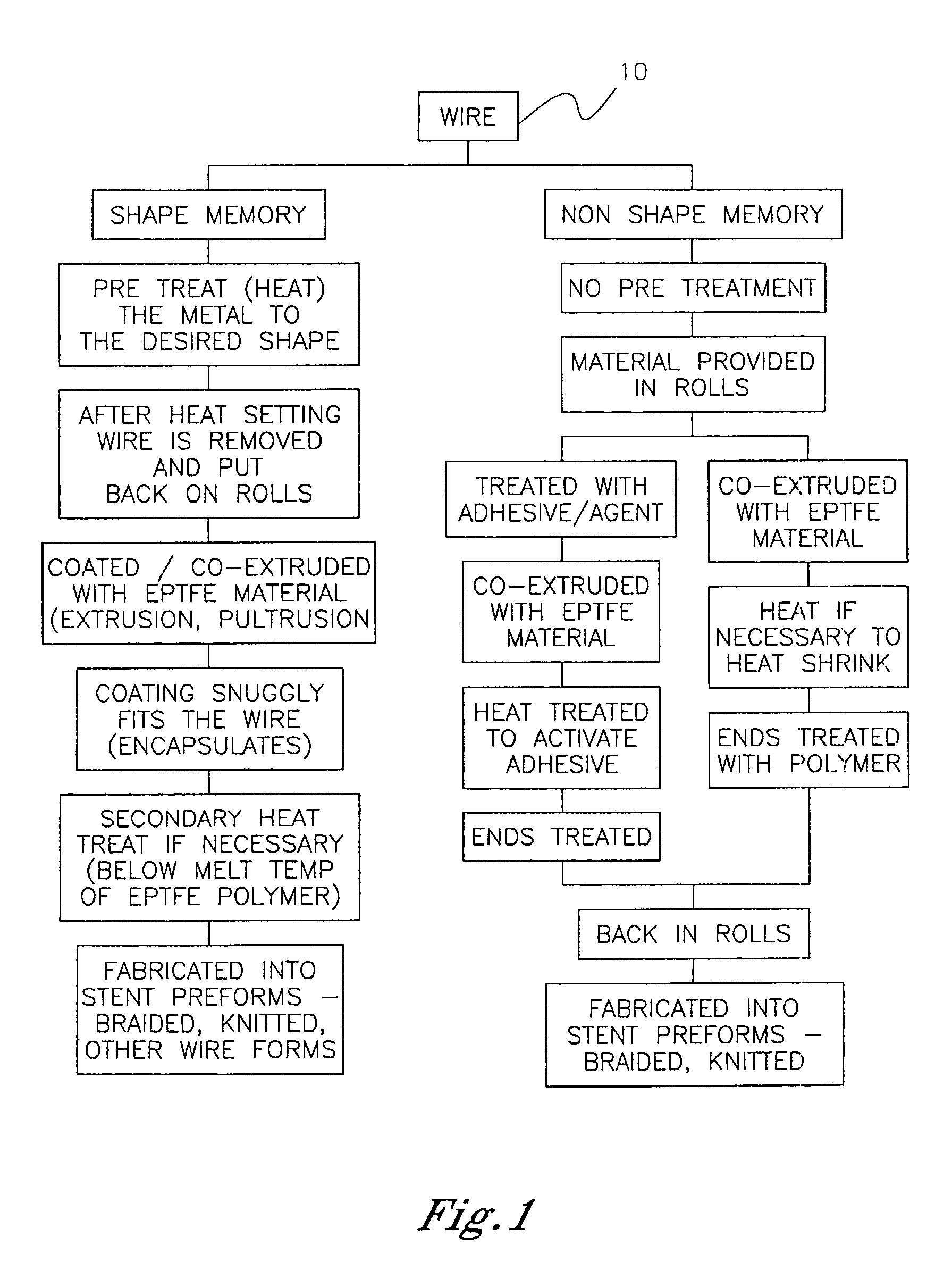
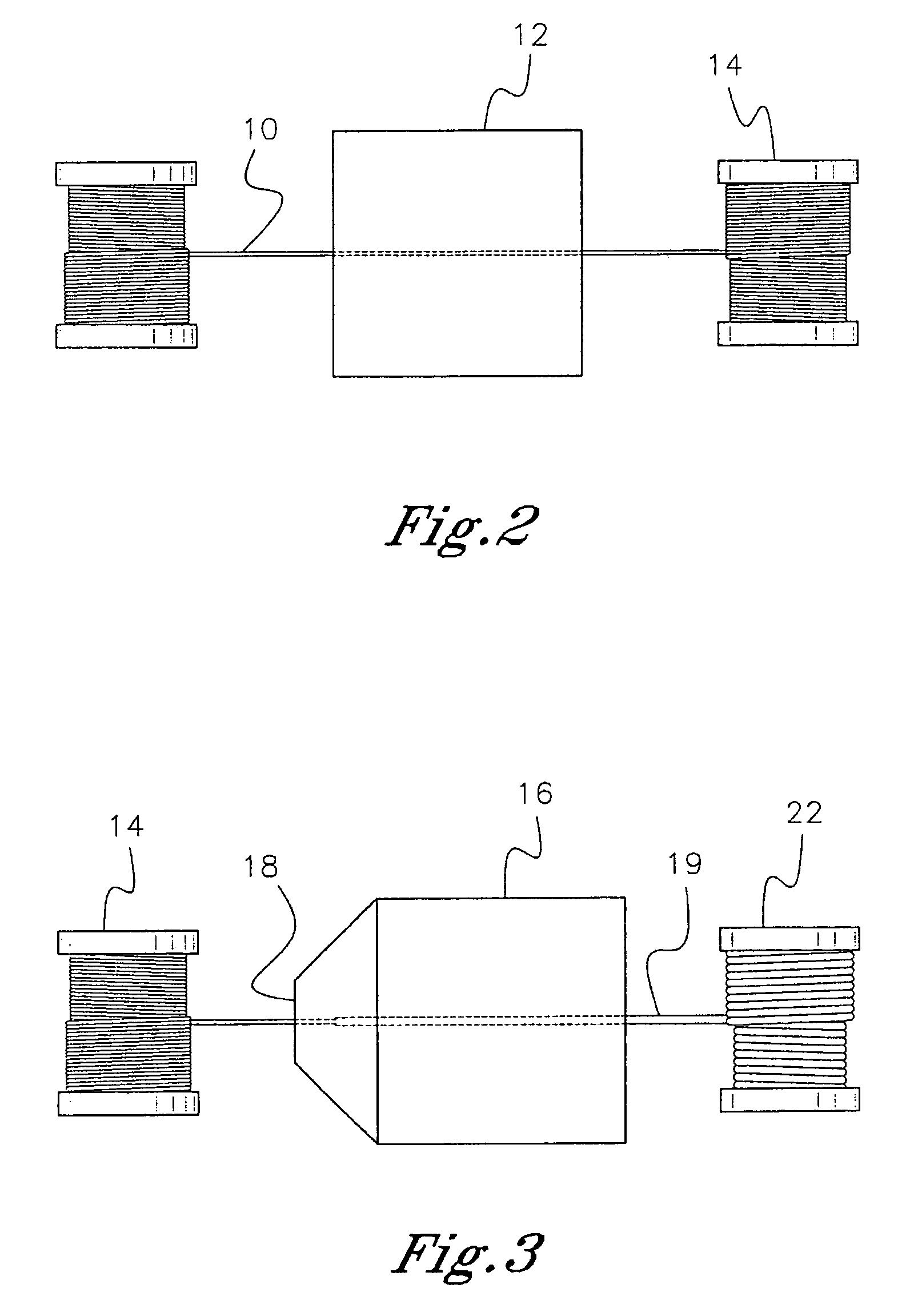
[0017]Referring to FIG. 1, an expandable wire 10 suitable for use in a stent is chemically treated to remove surface oxidation and is then shaped and preheated in an oven 12 as shown in FIG. 2 to impart a desired shape to the wire. Alternatively, a plurality of wire strands are introduced in the oven simultaneously, heat set, then removed and put back on individual spools. These spools are sent to the coating step shown in FIG. 3. Alternatively, as shown in FIG. 1, the fluoropolymer can be adhesively applied to the wire 10.

[0018]Typical wire 10 for use in this invention is nickel-titanium alloy known as NITINOL™, stainless steel, titanium, tungsten, platinum, gold, silver or other like malleable metal that will retain a memory after heat treatment.

[0019]After heat treating NITINOL™ between 500–600 degrees C. for two to ten minutes, the NITINOL™ wire 10 is respool...


PUM

PropertyMeasurementUnit
Speedaaaaaaaaaa
Shapeaaaaaaaaaa
Biocompatibilityaaaaaaaaaa

Abstract

A method for manufacturing a stent includes heating a plurality of wire strands to impart a desired shape to the wire strands, coating each wire strand with a biocompatible polymer in an extruder to produce a plurality of coated wire strands, and interlacing the coated wire strands to form a stent.

Description

CROSS-REFERENCE TO RELATED APPLICATION[0001]This application is a continuation of U.S. application Ser. No. 09 / 672,422, filed Sep. 28, 2000 now U.S. Pat. No. 6,652,574. Benefit of the earlier filing date is claimed in accordance with 35 U.S.C. §120.BACKGROUND OF THE INVENTION[0002]The present invention relates to wire stents and related vascular devices. More particularly, it refers to a stent or other vascular positioned device containing a wire coated with a biocompatible fluoropolymer.[0003]My prior application includes stents made from interwoven groups of yarn filaments containing a wire. U.S. Pat. No. 6,161,399 issued Dec. 19, 2000 and entitled, “Process for Manufacturing a Wire Reinforced Monolayer Fabric Stent” is hereby incorporated by reference. In addition, U.S. Pat. No. 5,961,545 describes wire stents immobilized longitudinally between tubes of expandable polytetrafluoroethylene. U.S. Pat. No. 5,957,954 describes braiding a stent and a polytetrafluoroethylene textile str...

Claims


Application Information

Patent Timeline
IPC IPC(8): A61F2/02A61F2/88A61F2/90
CPCA61F2/07D04B21/16A61F2/885A61F2/90Y10T29/49885Y10T29/49982Y10T29/4998A61F2002/072D10B2509/06
Inventor JAYARAMAN, SWAMINATHAN
Owner VASCULAR CONCEPTS HLDG
Why Eureka
Try Eureka