Coating film forming apparatus and coating unit

a technology of coating film and forming apparatus, which is applied in the direction of photomechanical equipment, vacuum evaporation coating, instruments, etc., can solve the problems of non-uniform film thickness of the entire wafer, high circumferential speed of the inner circumferential air turbulence at the outer peripheral portion of the wafer, so as to achieve the effect of increasing the yield of coating solution

Inactive Publication Date: 2005-08-30
TOKYO ELECTRON LTD
View PDF10 Cites 11 Cited by
  • Summary
  • Abstract
  • Description
  • Claims
  • Application Information

AI Technical Summary

Benefits of technology

[0010]The present invention is made in view of the aforesaid circumstances and its object is to provide a coating film forming apparatus capable of increasing yields of a coating solution and forming a uniform coating film, and a coating unit.
[0012]According to this invention, quick drying can be performed since drying is performed under reduced pressure even if a large amount of solvent remains in the coating solution applied to the substrate, and a temperature of the coating film within wafer can be maintained uniform by non-heating or heating at a low temperature even if heating is performed. Additionally, drying under reduced pressure can be quickly performed before volatilization of the solvent proceeds so far without waiting the main transfer mechanism after the application since the reduced-pressure drying section is provided in the coating unit, whereby the uniformity within the substrate in film thickness of the coating film can be maintained. Hence, it is possible to increase the yields of the coating solution and besides form the uniform coating film.
[0016]According to such invention, the volatilization of the solvent from the coating solution can be inhibited when the substrate after being applied is transferred by the main transfer mechanism, whereby it is possible to maintain the uniformity within the substrate in film thickness of the coating film. In this case, it is preferable that the main transfer mechanism has washing means for washing the holding member, for example, means for supplying a washing solution to the holding member and means for supplying gas for drying to the holding member. Further it is desirable that the main transfer mechanism has detecting means for detecting a stain of the holding member, since it is possible to determine the timing when the holding member is to be washed.
[0018]According to the coating unit, the concentration of the solvent atmosphere inside the container is detected by the sensor and a result of the detection by the sensor is inputted to the control means. Here, the control means operates the solvent-atmosphere generating means to generate the solvent atmosphere at the predetermined concentration inside the container when the concentration of the solvent atmosphere inside the container is lower than the predetermined concentration. On the other hand, when the concentration of the solvent atmosphere inside the container is higher than the predetermined concentration, the control means operates the intake means so that the solvent atmosphere inside the container is sucked. Accordingly, the concentration of the solvent atmosphere inside the container can be maintained constant since it is possible to rapidly cope with the concentration change of the solvent atmosphere.
[0019]According to the coating unit, it is possible to increase the yields of the coating solution and besides form the uniform coating film. In addition, it is possible to rapidly cope with the concentration change of the solvent atmosphere inside the container, thereby enabling the concentration of the solvent atmosphere to be maintained constant. As a result, formation of the film which is a thin film and uniform in film thickness can be realized and, for example, fabrication of a semiconductor device of high quality or the like is made possible. Further, a throughput can be improved. Moreover, it is possible to rapidly generate the solvent atmosphere at the predetermined concentration inside the container by supplying the solvent vapor and maintain the solvent atmosphere inside the container at the predetermined concentration by performing intake.
[0020]In the coating unit, the solvent-atmosphere generating means has a tank for storing the solvent therein and a heating mechanism for heating the solvent in the tank, and it is preferable that heating by the heating mechanism is controlled by the control means. According to such structure, the control means accelerates heating by the heating mechanism so that an amount supplied of the solvent vapor can be increased when the concentration of the solvent atmosphere inside the container is lower than the predetermined concentration. Therefore, it is possible to rapidly make the concentration of the solvent atmosphere inside the container the predetermined concentration.

Problems solved by technology

However, since the wafer is rotated at a high speed in the above-described method, there is a problem that a circumferential speed of the inner circumferential portion of the wafer becomes high compared with that of the outer circumferential portion thereof, whereby air turbulence occurs at the outer peripheral portion of the wafer particularly when the wafer is upsized.
The turbulence becomes a factor of impairing the formation of finer patterns since it changes the film thickness, bringing about the non-uniformity in film thickness of the entire wafer.
Further, the resist solution is spread to be blown off from the central portion of the wafer toward the peripheral portion thereof, causing a big waste of resist solution since it scatters from the peripheral portion thereof to the side of the cup.
In addition, there has been a problem that the resist solution applied to portions except for a circuit formation region such as the peripheral portion or the resist solution adhered to the cup due to the scatter is hardened, which results in a cause of particles.
Therefore, when the wafer is transferred to a heating plate and undergoes drying after being applied with the resist solution, it requires long time to volatilize the thinner, and an amount of volatilization varies within the wafer since it is hard to evenly conduct heat to the resist solution, whereby the uniformity in film thickness of the film to be obtained is deteriorated even if the resist solution is uniformly applied purposely.
Further, variations in the amount of volatilization within wafer become wide while the wafer is transferred to the heating plate by a main arm since the amount of volatilization is large on the wafer after being applied with the resist solution, also resulting in a factor which deteriorates the uniformity in film thickness of the resist film.

Method used


Image

  • Coating film forming apparatus and coating unit
  • Coating film forming apparatus and coating unit
  • Coating film forming apparatus and coating unit

Examples


first embodiment

[0060](First Embodiment)

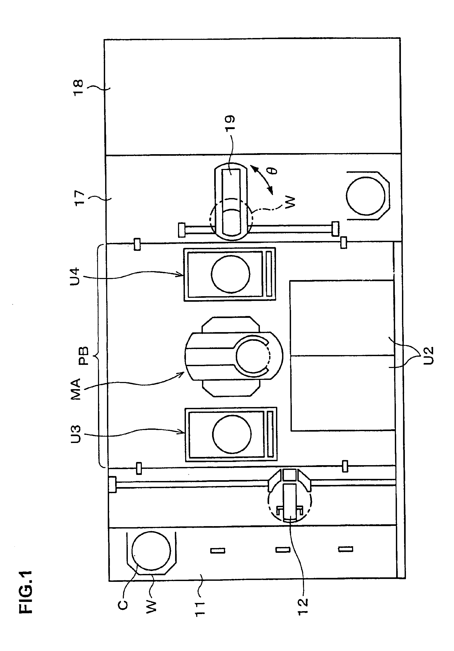
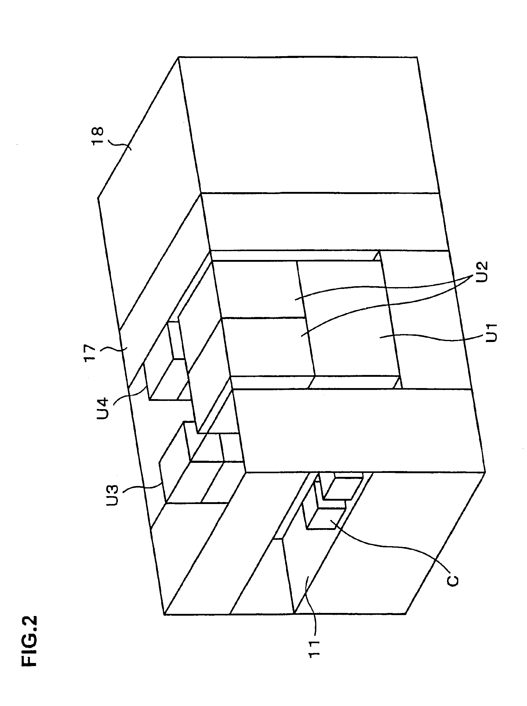
[0061]First, a general whole structure of a pattern forming apparatus will be briefly described with reference to FIG. 1 to FIG. 3. 11 is a cassette mounting section for carrying in / out a wafer cassette which is a substrate cassette, and, for example, a cassette C, in which 25 wafers W that are substrates are housed, is mounted thereon by, for example, an automatic transfer robot. In an area facing the cassette mounting section 11, a delivery arm 12 which is a delivery mechanism for the wafer W is provided to be movable in an X-, Z-, or Y-direction and rotatable in a θ-direction (rotatable about a vertical axis). Further, at the back side of the delivery arm 12, arranged are a coating unit U1 (see FIG. 2) and a developing unit U2, for example, on the right side when the back is seen from, for example, the cassette mounting section 11, and shelf units U3 and U4 are arranged at the near side and the backside, respectively.

[0062]The shelf units U3 and U4 are for...

second embodiment

[0088](Second Embodiment)

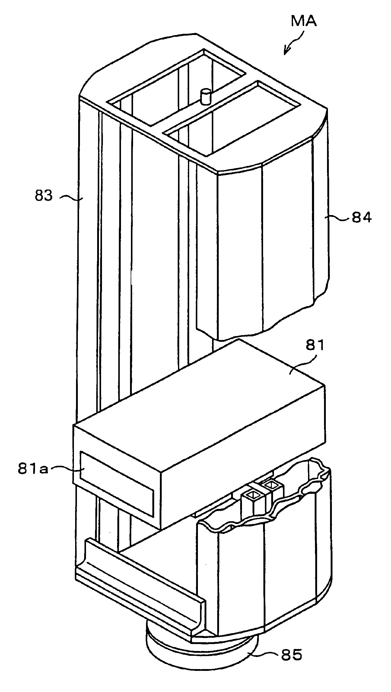
[0089]This embodiment aims at making the wafer holding portion 6 in the coating section 3 also serve as the mounting portion 41 in the reduced-pressure drying section 4, which are provided in the coating unit U1. FIG. 12 and FIG. 13 is a side view and a plane view respectively showing a coating unit U1 according to a second embodiment. In this example, the numeral representing a wafer holding portion is 7. The ball screw portion 63 and the guide portion 64 for moving the wafer holding portion 7 in the coating section 3 in the Y-direction project from the opening portion 31a of the case body 31 to the outside and extend to an area where drying under reduced pressure is performed. The wafer holding portion 7 is formed as a cylindrical table which is larger than the wafer W in size, and the peripheral portion of the wafer holding portion (mounting portion) 7 is air-tightly joined with the lid body 42 to form a closed container similarly to the mounting portion ...

third embodiment

[0094](Third Embodiment)

[0095]In this embodiment, the reduced-pressure drying sections are not provided in the coating unit U1 but are provided in the shelf unit U3 (U4) as processing units. FIG. 16 and FIG. 17 is a schematic plane view and a schematic side view respectively showing processing blocks of a pattern forming apparatus according to such embodiment, 17a are reduced-pressure drying units, and 18a is a coating film removing unit. Here, an example., in which a shelf unit U5 is added other than the shelf units U3 and U4 in order to reserve numbers of the heating units 13 or the like, is shown. In the coating section 3, the wafer holding portion 6 is structured so as to be carried from the case body 31 to a region of delivery where the wafer W is received and delivered from / to the main arm MA.

[0096]In this embodiment, the wafer W applied with the resist solution is taken out of the coating unit U1 by the main arm MA and transferred to the reduced-pressure drying unit U3, and t...


PUM

PropertyMeasurementUnit
diameteraaaaaaaaaa
pressureaaaaaaaaaa
pressureaaaaaaaaaa

Abstract

A coating film forming apparatus for forming a film by applying a coating solution to a substrate, which is provided with a cassette section, coating unit, developing unit, pre-treatment / post-treatment units and a main arm for transferring the substrate between the respective units. In the coating unit, provided is a coating section in which a resist is applied on the substrate in a manner of single stroke by intermittently moving the substrate in a Y-direction and by moving a nozzle in an X-direction, and provided is a reduced-pressure drying section for drying under reduced pressure the substrate after being applied, and further provided is equipment for removing the coating film adhered to a periphery of the substrate. Additionally, when the reduced-pressure drying section is arranged outside the coating unit, the main arm is covered with a cover so that the inside thereof is under a solvent atmosphere.

Description

CROSS-REFERENCE TO RELATED APPLICATIONS[0001]This application is a divisional of and claims priority to U.S. patent application Ser. No. 09 / 734,877, filed Dec. 13, 2000, now U.S. Pat. No. 6,676,757 which claims priority to Japanese Patent Application No. 11-359935, filed Dec. 17, 1999 and Japanese Patent Application No. 11-360990, filed Dec. 20, 1999. The entire contents of the U.S. patent application is incorporated herein by reference.BACKGROUND OF THE INVENTION[0002]The present invention relates to an apparatus for forming a coating film on a substrate to be treated such as a semiconductor wafer or an LCD substrate (a glass substrate for a liquid crystal display) by applying a coating solution, for example, a resist solution or the like thereto, and a coating unit.[0003]In fabrication processes of a semiconductor device or an LCD, a resist pattern for a substrate to be treated is formed by a technology called photolithography. An apparatus for forming the resist pattern is compos...

Claims


Application Information

Patent Timeline
Patent Type & Authority Patents(United States)
IPC IPC(8): G03F7/16H01L21/00H01L21/027
CPCG03F7/162H01L21/6715Y10S134/902
Inventor KITANO, TAKAHIROMORIKAWA, MASATERUESAKI, YUKIHIKOISHIZAKA, NOBUKAZUKOGA, NORIHISATAKESHITA, KAZUHIROOOKUMA, HIROFUMIAKIMOTO, MASAMI
Owner TOKYO ELECTRON LTD
Why Eureka
Try Eureka