Horizontal bore cryogenic drilling method

a cryogenic drilling and horizontal bore technology, applied in the direction of directional drilling, borehole/well accessories, lighting and heating apparatus, etc., can solve the problems of insufficient screen length, inability to produce water by traditional vertical wells, and inability to produce water by vertical wells as much, so as to prevent the collapse of the freeze zone, prevent the efficient flow of water, and large enough diameter

Active Publication Date: 2006-02-21
CH2M HILL +1
View PDF21 Cites 9 Cited by
  • Summary
  • Abstract
  • Description
  • Claims
  • Application Information

AI Technical Summary

Benefits of technology

[0015]A first aspect of the invention is a method of forming a horizontal bore in an earth formation. A pilot hole is formed of a first select diameter along a desired path of the horizontal bore. A grindable casing, preferably a high-density polyethylene casing, is inserted into the pilot hole. A cryogenic fluid is flowed through the grindable casing to form a freeze zone of frozen moisture adjacent to the grindable casing having a second selected diameter. A primary bore is formed having a third select diameter greater than the first select diameter and less than the second select diameter within the freeze zone along the desired path of the horizontal bore with the grindable casing in place. The second diameter is selected to be sufficiently greater than the third select diameter to prevent collapse of the freeze zone.
[0016]Forming of the pilot hole is preferably accomplished using a directionally controlled drill string driven by a cryogenic fluid or conventional drilling mud. Preferably, the bore is constructed from a ground surface overlying the earth formation and the horizontal bore includes a transverse portion transverse the ground surface and a horizontal portion substantially parallel to the ground surface. Preferably, for a water well completion, a screen or screen and gravel pack is installed in the horizontal portion of the primary bore while the freeze zone remains sufficiently frozen to prevent collapse of the primary bore. A casing is installed between the ground surface and the screen. A submersible pump may be installed in either the transverse portion or the horizontal portion. Alternatively, a vertical shaft may be provided between the ground surface and the horizontal portion of the bore and a pump may be provided proximate an intersection between the vertical shaft and the horizontal portion of the bore. In a highly preferred embodiment, the second select diameter defines a freeze zone of sufficient structural integrity to withstand mechanical forces of a directional drill string used in forming the primary bore as the primary bore transitions from the transverse portion to the horizontal portion without collapse of the primary bore.
[0017]A second aspect of the present invention is a method of forming a horizontal bore in an earth formation which includes providing a drill string having a conduit communicating with a cutting tool for engaging the earth formation. A cryogenic fluid is flowed through the conduit and the cutting tool to drive the cutting tool and remove cuttings from a bore formed by the cutting tool. The cutting tool is directed into an earth formation and a freeze zone is formed in the earth formation in advance of the cutting tool by the cryogenic fluid flowing through the cutting tool. The cutting tool is then advanced into the earth formation to form the horizontal bore at a rate enabling continued formation of a freeze zone in advance of the cutting tool of sufficient diameter to prevent collapse of the bore as the cutting tool is advanced.
[0018]The method may further include initially directing the cutting tool into the earth formation at a ground surface above the formation and advancing the cutting tool to form a transverse portion of the horizontal bore transverse to the ground surface and a horizontal portion of the horizontal bore substantially parallel to the ground surface. The freeze zone is preferably formed to have a large enough diameter that it has sufficient structural integrity to withstand mechanical forces of the drill string as the bore transitions from the transverse portion to the horizontal portion without collapse of the bore. The method may further include installing a well screen or well screen and gravel pack within the horizontal portion of the bore while the freeze zone remains sufficiently frozen to prevent collapse of the horizontal portion of the bore. A casing is installed to connect the screen to the surface. A submersible pump may be installed in one of the transverse portion or the horizontal portion of the well bore. Alternatively, a vertical shaft may be provided between the ground surface and the horizontal portion of the bore. A vertical line shaft or submersible pump is then provided proximate to an intersection between the vertical shaft and the horizontal portion of the bore.
[0019]The horizontal bore cryogenic drilling method in accordance with the present invention eliminate the need to use conventional drilling muds which can both pollute the earth formations around a well screen and plug the formation to prevent the efficient flow of water into a horizontal well bore. The cryogenic fluid further allows freezing of formation around the bore hole which allows the earth formation to take on the character of hard rock. This not only improves the structural integrity in the vicinity of the bore, but it eliminates infiltration of formation fluid and eliminates exfiltration of drilling fluids. The cryogenic technique further provides a solid formation which enables the use of drilling hammers as an alternative to rotary drills which can speed construction of the bore. In addition, the frozen cuttings act like dry powdered rock, which can be more efficiently removed from a bore by a cryogenic drilling fluid. The technique also eliminates the need to install grouted casings across the radius of the bore hole where it transfers from transverse to horizontal, thus further speeding and simplifying construction of the bore. In addition, the cryogenic technique renders irrelevant encountering cohesive soils such as clay which might otherwise form problematic clay balls. Finally, physical changes to the formation around the bore hole created by the cryogenic method are temporary. The formation will revert to its natural conditions shortly after circulation of the cryogenic fluid is stopped. By way of contrast, mud rotary methods require elaborate well development processes to remove the mud invasion from the formation and these processes have proven unsatisfactory.

Problems solved by technology

In many aquifers, the ability to produce water by traditional vertical wells is limited by several factors.
In the case of thin aquifers, vertical wells do not allow a long enough section of screen to be installed across the productive formation.
Both of these factors prevent vertical wells from producing as much water as could be potentially extracted.
These obstructions typically include rivers, lakes, wetlands, structures or other areas where a wellhead is not permitted or access for a vertical drilling rig is impractical.
Building a radial horizontal collector well using this conventional construction technique is a difficult and lengthy undertaking.
For this reason, radial horizontal collector wells are often several times the cost of a traditional vertical well.
In addition, the laterals cannot generally be steered or directed other than by simple linear protection from the caisson.
The method has limited ability to project laterals through boulders, cobbles or other obstruction or difficult drilling conditions.
An additional problem with this conventional construction technique is fluid invasion into the open face of the lateral cannot be controlled during construction.
This forces workers to endure wet conditions in a confined space below the water table with all the inherent risks and safety hazards that can occur under such conditions.
While the use of drilling mud is necessary for the construction of the bore hole, either type of mud produces undesirable effects on the formation around the bore hole.
As it penetrates the formation, the mud creates a zone of invasion which reduces the permeability of the formation adjacent to the bore hole.
This has the desirable effect of reducing infiltration of formation water into the bore hole during well construction, but also creates a zone of low permeability that limits the ability of water to flow into the bore hole after construction is completed.
In these applications, the zone of low permeability created by mud invasion significantly reduces the production capacity of the well.
To date, efforts to remove the drilling mud from the invaded zone have proven to be expensive and of only limited effectiveness.
Additional limitations of horizontal directionally drilled borings using drilling muds are commonly encountered.
The method has limited ability to prevent collapse of the bore hole in formations containing cobbles and loose gravel.
This can cause the formation to collapse on the drilling string.
In addition, there is a tendency for cuttings to settle out of the mud forming an obstruction on the bottom of the horizontal portion of the hole.
In many applications, the formations lack the structural integrity to withstand the stress as the drill rod is forced into the formation at the top of the bore hole.
This increases the cost and complexity of the drilling operation.
In the drilling of vertical wells, problems of contamination of the area adjacent the well bore by drilling muds has been recognized.
Also, where vertical wells have been drilled in earth formations having a high water content, problems have been experienced in extracting water fast enough to effectively advance the drill.
In addition, particularly in places where certain shales swell or hydrate in the presence of an influx of water into the well bore, problems have been encountered with the shale becoming loosened and sloughing into the hole necessitating large quantities of shale and cuttings to be lifted out of the well bore.
Indeed, if enough shale is loosened, the drill string may even become stuck.
However, there is no suggestion in these references of the desirability of using vertical cryogenic well drilling techniques for the construction of horizontal bores.
The technique of Rebhan does not allow for construction of cryogenic horizontal wells from the ground surface, nor does it allow the use of directionally controlled drilling equipment.

Method used


Image

  • Horizontal bore cryogenic drilling method
  • Horizontal bore cryogenic drilling method
  • Horizontal bore cryogenic drilling method

Examples


Embodiment Construction

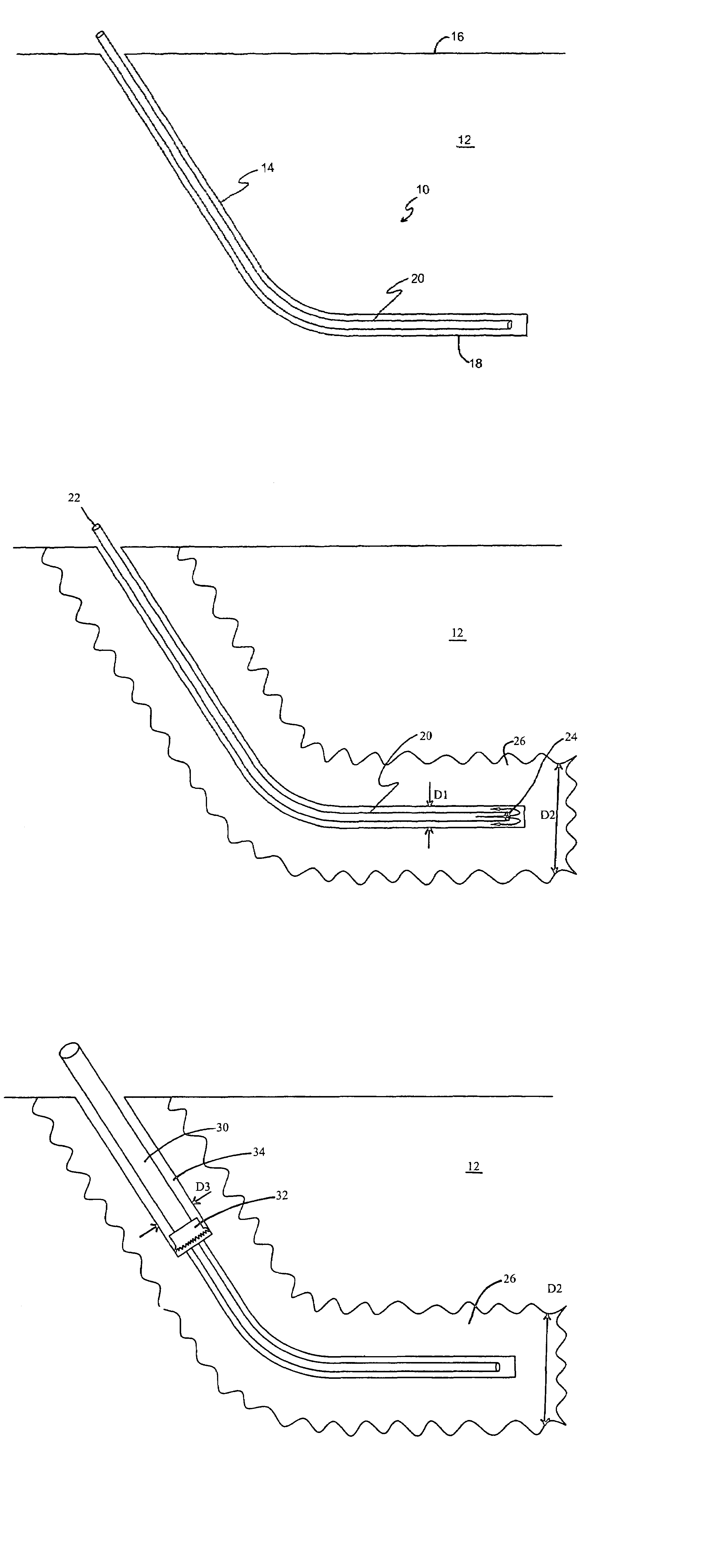
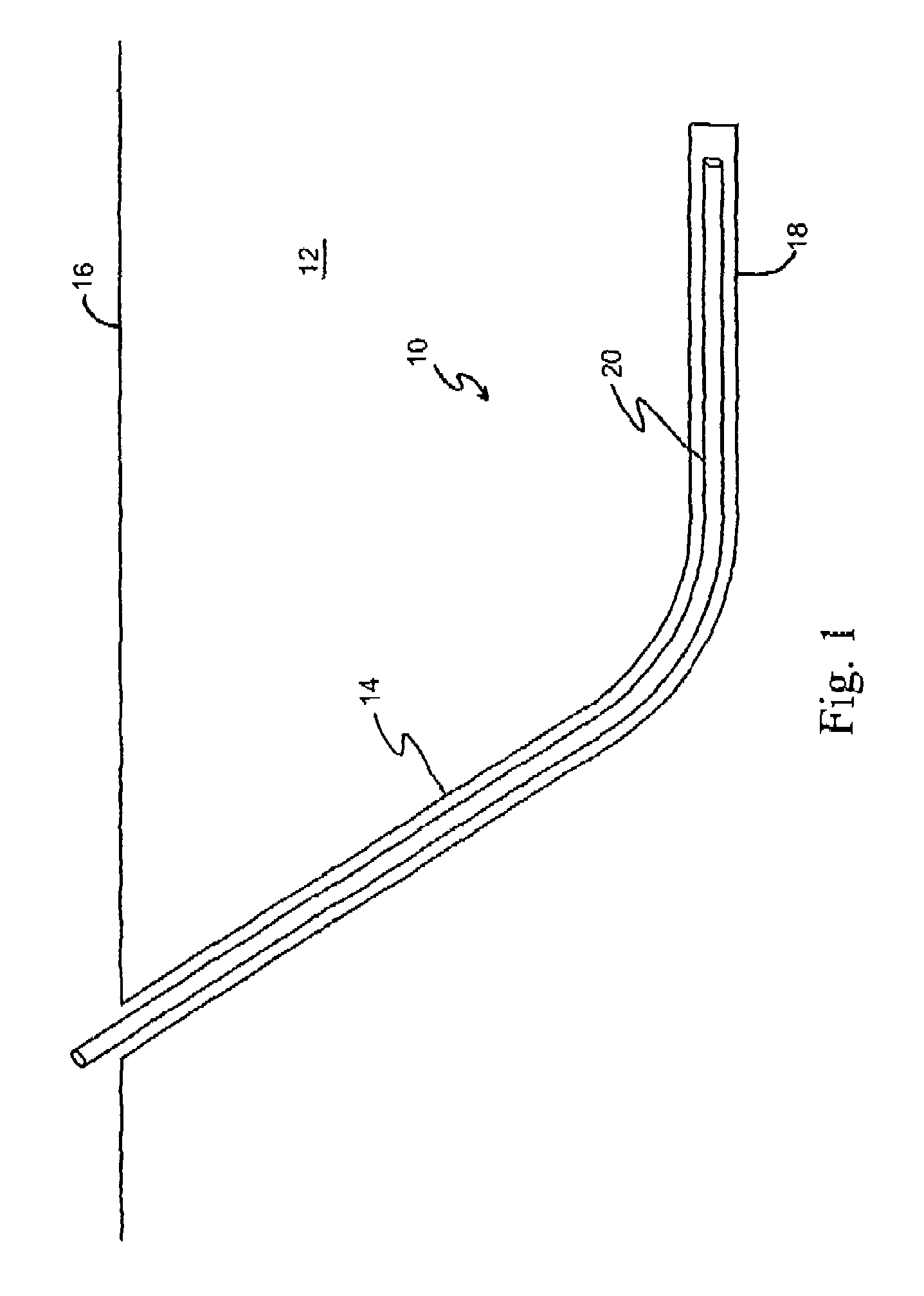
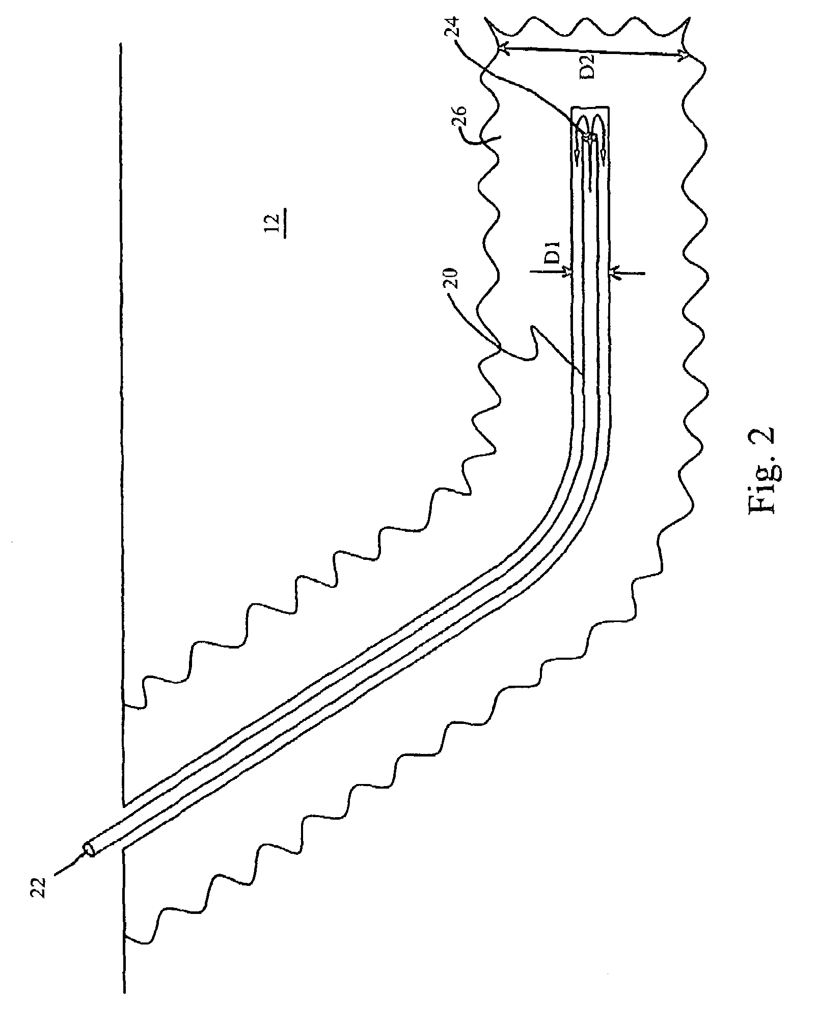
[0028]The present is invention contemplates the use of standard horizontal directional drilling equipment with only minor modifications to accommodate the cryogenic fluid. One representative manufacturer of horizontal directional drills is the Vermeer Manufacturing Company of Pella, Iowa. These horizontal directional drills allow the formation of bores having an initial portion transverse a surface of the earth which then transitions to a horizontal portion of a horizontal bore.

[0029]As mentioned above, use of cryogenic fluids may require modifications to standard horizontal directional rigs. For example, it will likely be necessary to provide a substitute material for low carbon steel used in conventional drill strings because the low carbon steel may become too brittle at cryogenic temperatures. For vertical drill strings, use of aluminum drill pipe or steel pipe containing 9% or more nickel has been suggested. Weaver, U.S. Pat. No. 3,774,701, at column 2, line 68–73. Use of cryog...


PUM


Abstract

A horizontal bore cryogenic drilling method includes in a first embodiment forming a pilot hole of a first select diameter along a desired path of the horizontal bore. A grindable casing is inserted into the guide bore. A cryogenic fluid is flowed through the grindable casing to form a freeze zone of frozen moisture adjacent the grindable casing having a second select diameter. A primary bore is formed having a third select diameter greater than the first diameter and less than the second select diameter within the freeze zone along the desired path of the horizontal bore with the grindable casing in place. The second diameter is selected to be sufficiently greater than the third select diameter to prevent collapse of the freeze zone. Another embodiment of the invention is a method of forming a horizontal bore in an earth formation including providing a drill string having a conduit communicating with a cutting tool for engaging the earth formation. A cryogenic fluid is flowed through the conduit and the cutting tool to drive the cutting tool and remove cuttings from a bore formed by the cutting tool. The cutting tool is directed into an earth formation and a freeze zone is formed in the earth formation in advance of the cutting tool by the cryogenic fluid flowing through the cutting tool. The cutting tool is then advanced into the earth formation to form the horizontal bore at a rate enabling continuous formation of a freeze zone in advance of the cutting tool of sufficient diameter to prevent collapse of the bore as the cutting tool is advanced.

Description

TECHNICAL FIELD[0001]The present invention is directed toward drilling bores in earth formations, and more particularly to a horizontal bore cryogenic drilling method.BACKGROUND ART[0002]In many aquifers, the ability to produce water by traditional vertical wells is limited by several factors. In the case of thin aquifers, vertical wells do not allow a long enough section of screen to be installed across the productive formation. This limits the area of the seepage base that can transmit water into the well and reduces the amount of available drawdown that can be created to induce flow toward the well. Both of these factors prevent vertical wells from producing as much water as could be potentially extracted. In other cases, the most productive portion of the aquifer is located under a physical obstruction where a vertical well cannot be installed. These obstructions typically include rivers, lakes, wetlands, structures or other areas where a wellhead is not permitted or access for ...

Claims


Application Information

Patent Timeline
Patent Type & Authority Patents(United States)
IPC IPC(8): E21B7/00E21B7/08E02D29/00E21B7/04
CPCE21B7/046E21B7/00
Inventor MILLER, THOMAS J.JANSEN, JOHN R.
Owner CH2M HILL
Why Eureka
Try Eureka