Electropipettor and compensation means for electrophoretic bias

a technology of electrophoretic bias and electrophoretic bias, which is applied in the field of microfluidic systems, can solve the problems of undesirable alteration or “electrophoretic bias” in the subject material, and achieve the effect of easy introduction

Inactive Publication Date: 2006-02-21
CAPLIPER LIFE SCI INC
View PDF52 Cites 13 Cited by
  • Summary
  • Abstract
  • Description
  • Claims
  • Application Information

AI Technical Summary

Benefits of technology

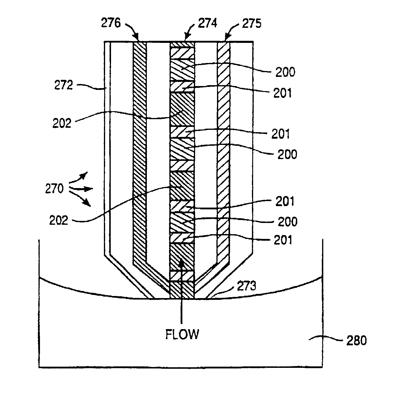
[0011]The present invention also provides for a electropipettor which is compatible with a microfluidic system which moves subject materials with electroosmotic forces. The electropipettor has a capillary having a channel. An electrode is attached along the outside length of the capillary and terminates in a electrode ring at the end of the capillary. By manipulating the voltages on the el

Problems solved by technology

However, where simple fluid transport is desired, these varied mobilities can resu

Method used


Image

  • Electropipettor and compensation means for electrophoretic bias
  • Electropipettor and compensation means for electrophoretic bias
  • Electropipettor and compensation means for electrophoretic bias

Examples


example 1

Forced Co-Migration of Differentially Charged Species, in Electropipettor-Type Format

[0102]In order to demonstrate the efficacy of methods used to eliminate or reduce electrophoretic bias, two oppositely charged species were electrokinetically pumped in a capillary channel, and comigrated in a single sample plug. A Beckman Capillary Electrophoresis system was used to model the electrophoretic forces in a capillary channel.

[0103]In brief, a sample containing benzylamine and benzoic acid in either low ionic concentration (or “low salt”) (5 mM borate), or high ionic concentration (“high salt”) (500 mM borate) buffer, pH 8.6, was used in this experiment. The benzoic acid was present at approximately 2× the concentration of the benzylamine. All injections were timed for 0.17 minutes. Injection plug length was determined by the injection voltage, 8 or 30 kV. The low salt and high salt buffers were as described above.

[0104]In a first experiment, three successive injections of sample in low...

example 2

Migration of Subject Materials through Electropipettor into Microfluidic System Substrate

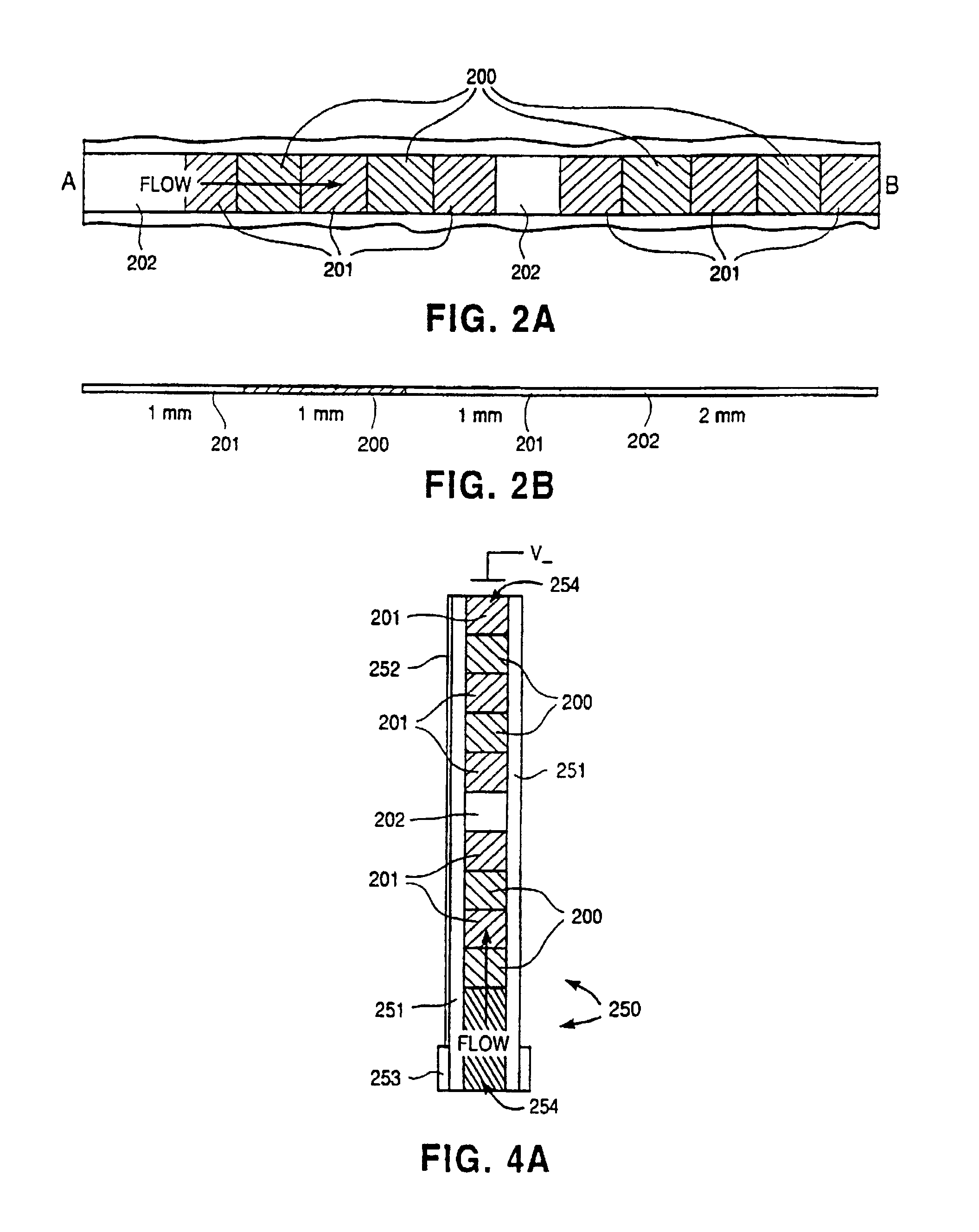
[0107]FIGS. 9A–9C illustrate the experimental test results of the introduction of a subject material, i.e., a sample, into a microfluidic system substrate through an electropipettor as described above. The sample is rhodamine B in a phosphate buffered saline solution, pH 7.4. A high ionic concentration (“high salt”) buffer was also formed from the phosphate buffered saline solution, pH 7.4. A low ionic concentration (“low salt”) buffer was formed from 5 mM Na borate, pH 8.6, solution.

[0108]In the tests subject material regions containing the fluorescent rhodamine B were periodically injected into the capillary channel of an electropipettor which is joined to a microfluidic system substrate. High salt and low salt buffers were also injected between the subject material regions, as described previously. FIG. 9A is a plot of the fluorescence intensity of the rhodamine B monitored at a point along t...


PUM

PropertyMeasurementUnit
Lengthaaaaaaaaaa
Lengthaaaaaaaaaa
Diameteraaaaaaaaaa

Abstract

A channel (140) is divised into portions (142, 144). The sidewalls of each channel portion (142, 144) have surface charges of opposite polarity. The two channel portions (142, 144) are physically connected together by a salt bridge (133), such as a glass frit or gel layer. The salt bridge (133) separates the fluids in channel (140) from an ionic fluid reservoir (135). To impart electroosmotic and electrophoretic forces along the channel (140) between parts A and B, respectively. Additionally, a third electrode (137) is placed in the reservoir (135).

Description

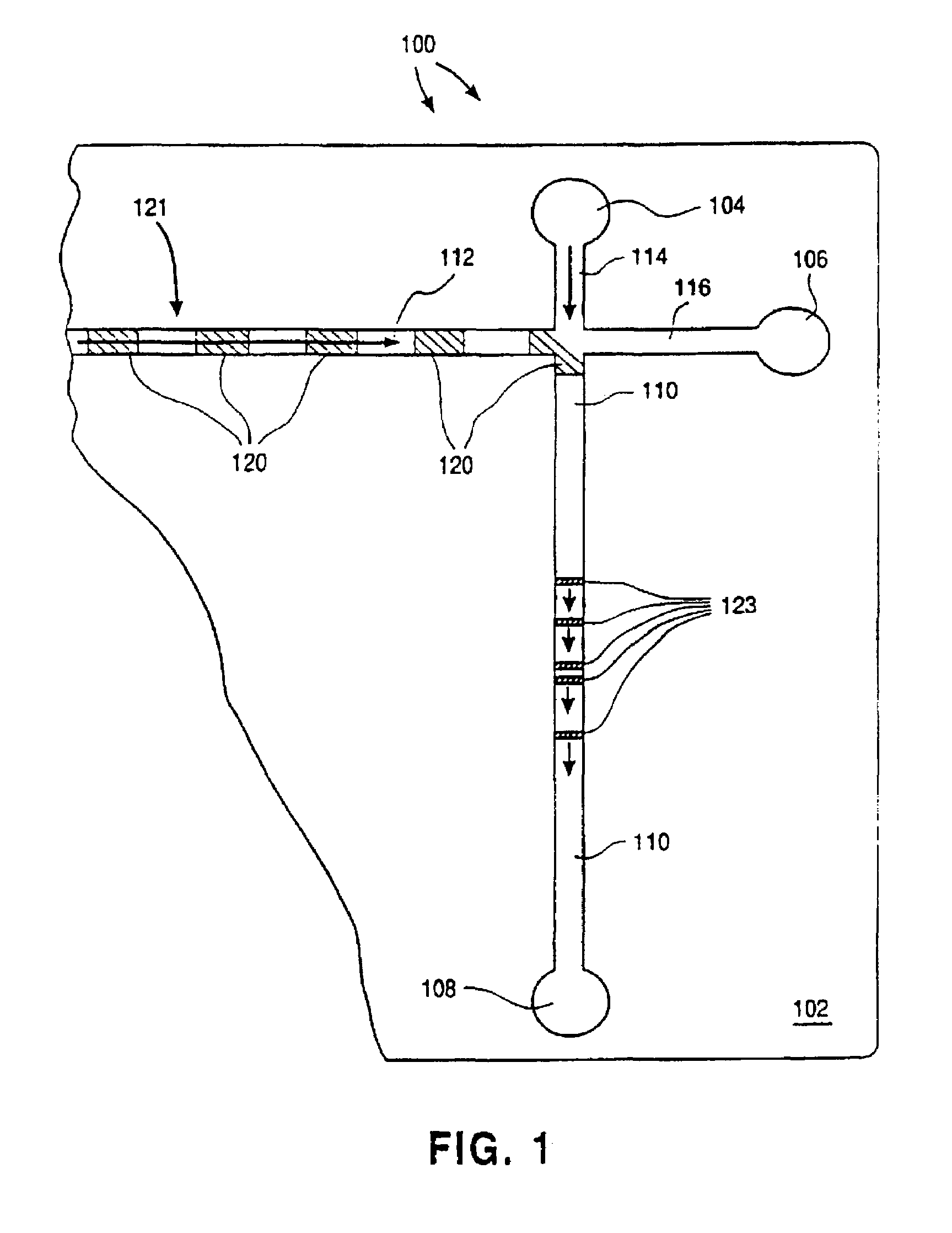
CROSS-REFERENCE TO RELATED APPLICATIONS[0001]This application is a continuation of U.S. patent application Ser. No. 09 / 202,993, filed Jul. 23, 1999, now U.S. Pat. No. 6,547,942, which is a 371 of PCT / US97 / 10963, filed Jun. 25, 1997, which is a continuation-in-part of U.S. patent application Ser. No. 08 / 760,446, filed Dec. 6, 1996, now U.S. Pat. No. 5,880,071, and a continuation-in-part of U.S. patent application Ser. No. 08 / 671,986, filed Jun. 28, 1996, now U.S. Pat. No. 5,779,868, all of which are incorporated herein by reference in their entirety for all purposes.BACKGROUND OF THE INVENTION[0002]There has been a growing interest in the manufacture and use of microfluidic systems for the acquisition of chemical and biochemical information. Techniques commonly associated with the semiconductor electronics industry, such as photolithography, wet chemical etching, etc., are being used in the fabrication of these microfluidic systems. The term, “microfluidic”, refers to a system or dev...

Claims


Application Information

Patent Timeline
IPC IPC(8): G01N27/453B01L3/02B01F13/00G01N31/20B01J19/00B01L3/00F04B17/00F04B19/00G01N27/26G01N27/447G01N37/00H02N11/00
CPCB01F13/0071B01J19/0093B01L3/502715B01L3/50273B01L3/502784F04B17/00F04B19/006G01N27/44704G01N27/44743G01N27/44791H02N11/006Y10T436/2575B01F13/0086B01J2219/00891B01L3/021B01L2200/027B01L2400/0415B01L2400/0418B01L2400/0421Y10S366/02Y10T436/113332B01F13/0084B01F33/3021B01F33/30351B01F33/30352
Inventor PARCE, J. WALLACEKNAPP, MICHAEL R.
Owner CAPLIPER LIFE SCI INC
Why Eureka
Try Eureka