
Apparatus and method for forming deposited film

a technology of deposited film and apparatus, applied in the direction of fluid loss/gain rate measurement, fluid tightness measurement, instruments, etc., can solve the problems of reducing the operating efficiency of apparatus in some cases, tightness degrades, and the yield of deposited film is reduced, so as to achieve good reproducibility without reducing the yield

Inactive Publication Date: 2006-02-21
CANON KK
View PDF16 Cites 4 Cited by
  • Summary
  • Abstract
  • Description
  • Claims
  • Application Information

AI Technical Summary

Benefits of technology

[0011]An object of the present invention is to provide an apparatus and method for forming a deposited film which can repeatedly form a large amount of functional deposited films with good reproducibility without degradation in the characteristics of films formed even when gas leakage occurs in a shut-off valve, and without reducing the yield as a result when gas leakage occurs in the shut-off valve, because it can be detected and repaired immediately.
[0014]The deposited film forming apparatus according to the present invention is constructed as described above, whereby the characteristics of the deposited film are not degraded even when gas leakage occurs in a shut-off valve, and when it occurs in the shut-off valve, gas leakage can be detected and repaired immediately. As a result, it has become possible to repeatedly form a large amount of functional deposited films with good reproducibility without decreasing the yield.

Problems solved by technology

However, in the case where an apparatus for producing, for example, a solar cell comprising amorphous silicon for the purpose of power generation is continuously operated by using a large amount of the source gas, there arises a problem.
However, even when for this shut-off valve, a valve of vacuum specification may be used, the tightness will be degraded with years of use to cause leakage (gas leakage from the upper stream of the shut-off valve toward the downstream).
Further, since it is very difficult to find out whether or not any gas leakage in the shut-off valve occurs, it will reduce the yield of the deposited film, and since it takes time to diagnose, the apparatus operating efficiency will be reduced in some cases.
Particularly, in an apparatus using the roll-to-roll method for the purpose of mass production, it has a number of chambers, a number of shut-off valves is also increased accordingly, and the probability of occurrence of gas leakage is also increased.
Also, it is difficult to identify a shut-off valve in which gas leakage occurs, and it takes time to diagnose, and heavy damage due to reduced yield and decreased operating efficiency will be caused.

Method used


Image

  • Apparatus and method for forming deposited film
  • Apparatus and method for forming deposited film
  • Apparatus and method for forming deposited film

Examples


embodiment 1

(Embodiment 1)

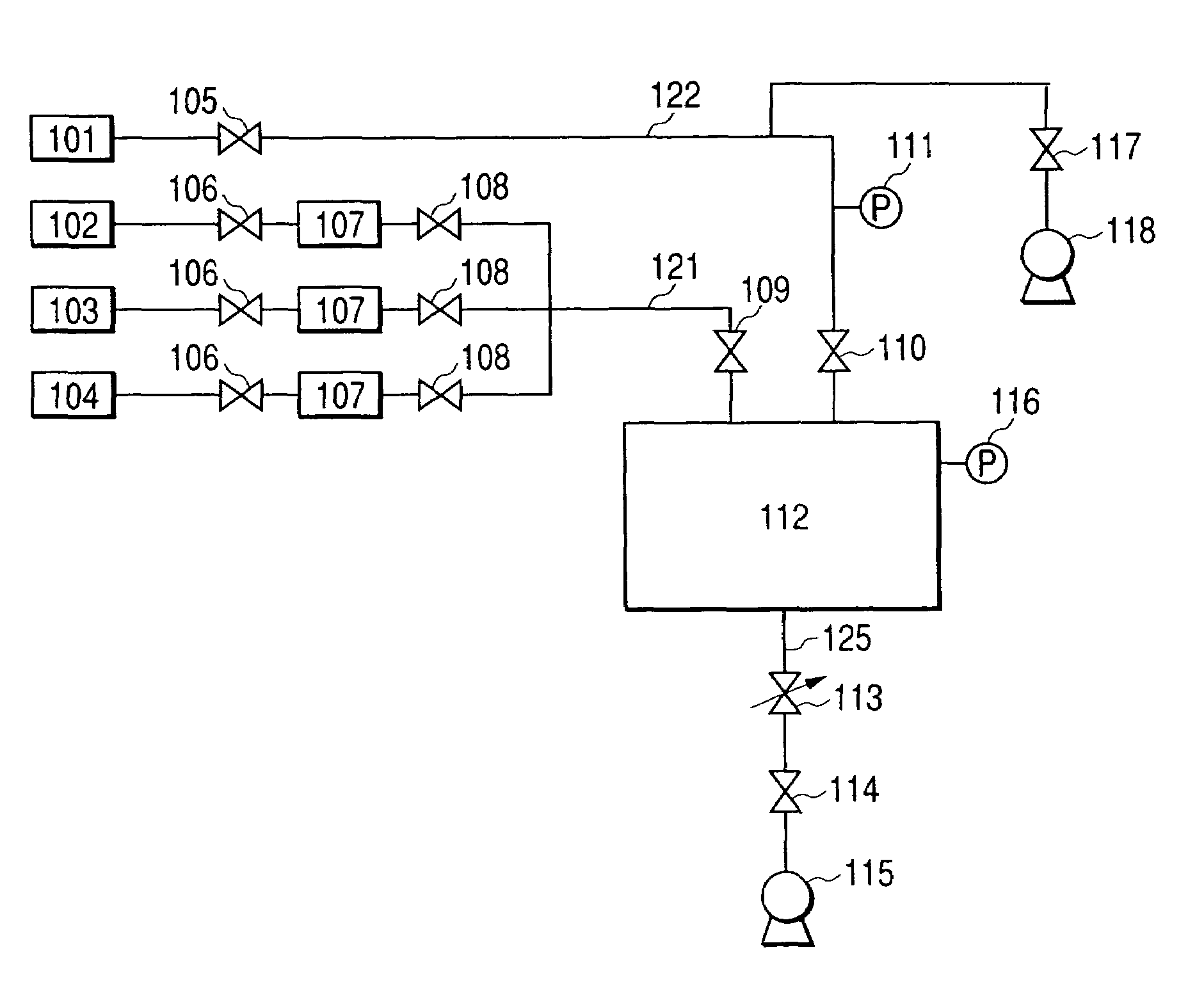
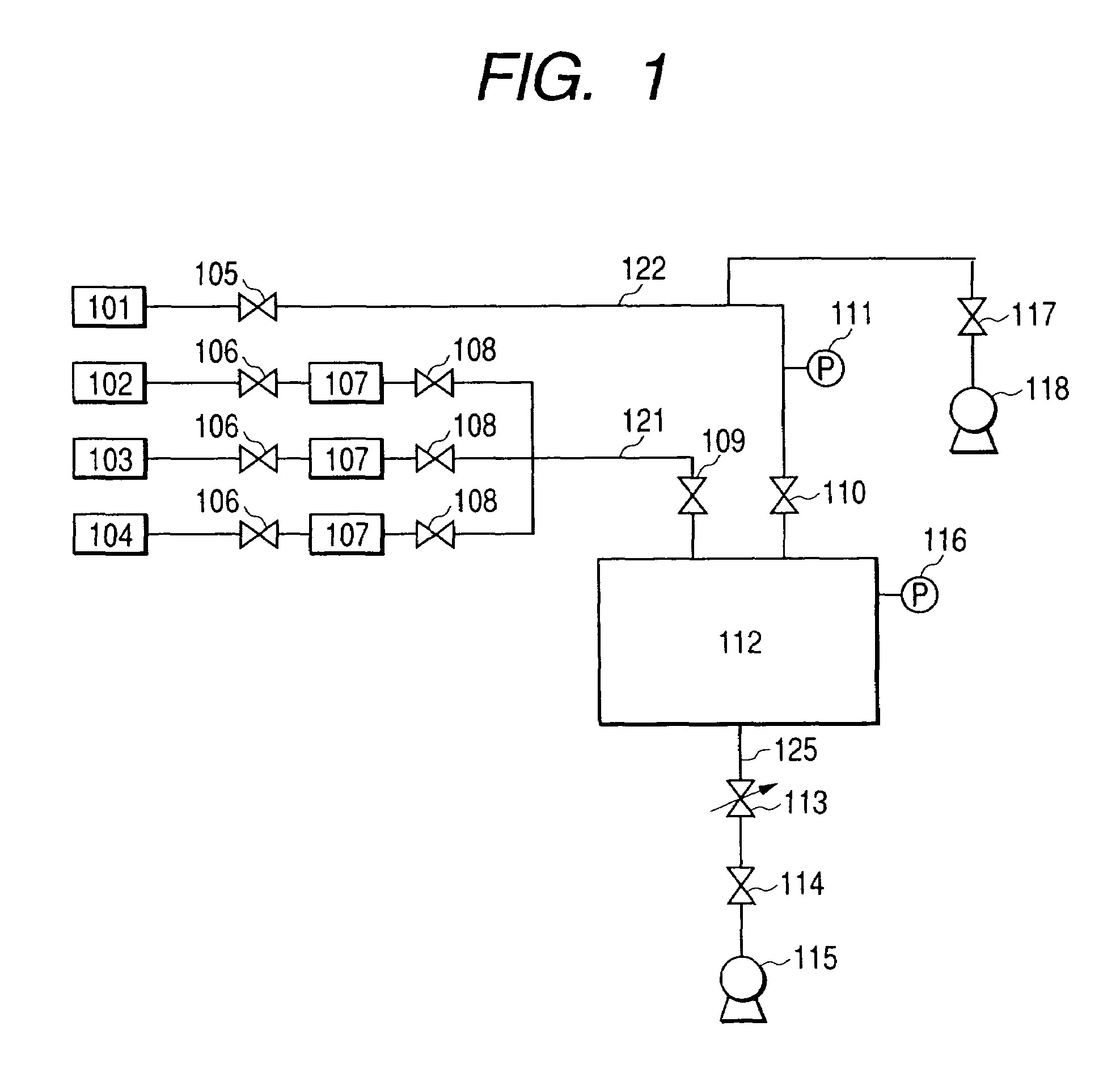
[0020]With reference to FIG. 1, embodiments of the present invention will be described specifically.

[0021]In FIG. 1, a reference numeral 101 denotes a gas source of a non-reactive gas (which is called “gas for opening to atmosphere” for the sake of convenience. Even if this gas is introduced, the chamber is not always opened to atmosphere) for returning the pressure within the chamber 112 to atmospheric pressure.

[0022]This non-reactive gas is supplied from the gas source 101 to a chamber 112 through a gas supply piping 122 for opening to atmosphere. In the gas supply piping 122 for opening to atmosphere, there are provided two shut-off valves 105 and 110. Between those two shut-off valves 105 and 110, there is provided a pressure gauge 111. Also, as needed, it is also possible to provide an evacuating means capable of evacuating a space of a piping between two shut-off valves 105 and 110 independently of the chamber, in the piping between the shut-off valves 105 and 11...

embodiment 2

(Embodiment 2)

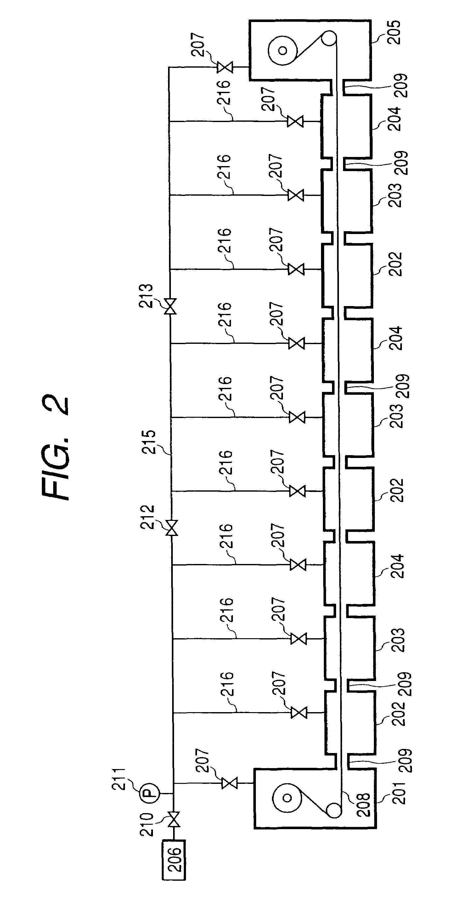
[0038]FIG. 2 shows another embodiment of the present invention. A deposited film forming apparatus according to the present embodiment is a solar cell mass-production apparatus having a plurality of chambers 202, 203 and 204, for repeatedly performing formation of amorphous silicon solar cell having three-layer structure of nip / nip / nip according to the roll-to-roll method.

[0039]A reference numeral 206 denotes a gas source for returning the pressure within the chamber to atmospheric pressure, and to this gas source 206, a main gas supply piping 215 for opening to atmosphere is connected through a shut-off valve 210. Further, from the main gas supply piping 215 for opening to atmosphere, branch pipes diverge toward each chamber 202, 203 and 204, and each branch pipe is connected to the chambers 202, 203 and 204 through the shut-off valve 207.

[0040]Also, at a position on the downstream side of the shut-off valve 210 of the main gas supply piping for opening to atmosphere,...

example 1

[0048]The apparatus shown in FIG. 1 was used, and silane gas of 150 sccm and hydrogen gas of 1000 sccm were supplied to deposit an amorphous silicon film on a SUS substrate. In accordance with the procedure shown in the above-described embodiment, deposited films were repeatedly formed. In this respect, evacuation was performed through the use of evacuating means 118. When repeated 300 times, a pressure gauge 211 located between the shut-off valves indicated a rise from 0 mTorr to 10 Torr during formation of a deposited film. After the formation of film, when the shut-off valve was removed from the piping for investigation, it was found that gas leakage had occurred. Also, an amorphous silicon film formed when gas leakage has occurred was investigated for electrical characteristics with the film as a single film, and as a result, it was an excellent film.


PUM


Abstract

The object of the present invention is to provide an apparatus and method for forming a deposited film which can repeatedly form a large amount of functional deposited films with good reproducibility without degradation in the characteristics of films formed even when gas leakage occurs in a shut-off valve, and without reducing the yield as a result when gas leakage occurs in the shut-off valve, by immediately detecting and repairing it. The deposited film forming apparatus according to the present invention comprises: a chamber capable of maintaining an interior thereof under vacuum; a source gas supply piping for supplying a source gas into the chamber; an evacuation system piping for evacuating the interior of the chamber; a gas supply piping for use in opening to atmosphere, for supplying a gas for returning a pressure within the chamber to atmospheric pressure, wherein a plurality of shut-off valves are provided in series between a gas source of the gas for returning the pressure within the chamber to the atmospheric pressure and the chamber, and a pressure-gauge and / or evacuating means are provided between the plurality of shut-off valves.

Description

[0001]This application is a division of application Ser. No. 09 / 867,493, filed on May 31, 2001 now U.S. Pat. No. 6,660,094.BACKGROUND OF THE INVENTION[0002]1. Field of the Invention[0003]The present invention relates to an apparatus and a method for forming a functional deposited film for use in, for example a solar cell, on a substrate, and particularly to an apparatus and a method for forming a deposited film suitable for mass production which repeatedly uses a large amount of a source gas for many hours.[0004]2. Related Background Art[0005]Conventionally, as a functional deposited film for a solar cell, an electrophotographic light-receiving member and the like, there have been proposed and put to practical use amorphous silicon, microcrystal silicon and the like. As a method for producing these materials, there have been proposed various methods, but a method based on plasma using electromagnetic wave such as high frequency and microwave has generally been used.[0006]In such a d...

Claims


Application Information

Patent Timeline
IPC IPC(8): C23C16/00C23C16/44C23C16/54
CPCC23C16/545C23C16/4402Y10T137/0452
Inventor OTOSHI, HIROKAZUIZAWA, HIROSHITANAKA, MASATOSHI
Owner CANON KK
Learn More