Semiconductor package having conductive bumps on chip and method for fabricating the same
- Summary
- Abstract
- Description
- Claims
- Application Information
AI Technical Summary
Benefits of technology
Problems solved by technology
Method used
Image
Examples
first preferred embodiment
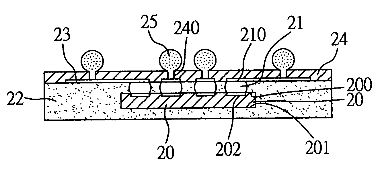
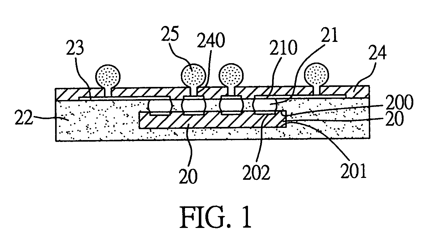
[0021]As shown in FIG. 1, the semiconductor package according to the invention comprises: at least one chip 20 having an active surface 200 and an opposite inactive surface 201, and having a plurality of bond pads 202 formed on the active surface 200; a plurality of conductive bumps 21 respectively formed on the bond pads 202 of the chip 20; an encapsulation body 22 for encapsulating the chip 20 and the conductive bumps 21, wherein ends 210 of the conductive bumps 21 are exposed outside of the encapsulation body 22; a plurality of conductive traces 23 formed on the encapsulation body 22 and electrically connected to the exposed ends 210 of the conductive bumps 21; a solder mask layer 24 applied over the conductive traces 23 and having a plurality of openings 240 for exposing predetermined portions of the conductive traces 23; and a plurality of solder balls 25 respectively formed on the exposed portions of the conductive traces 23.
[0022]The above semiconductor package can be fabrica...
second preferred embodiment
[0034]FIG. 3 shows a semiconductor package according to a second preferred embodiment of the invention. As shown, this semiconductor package is structurally similar to that of the first embodiment, with the difference in that during the grinding process of FIG. 2E, besides grinding the surface 220 of the encapsulation body 22 that is flush with the ends 210 of the conductive bumps 21, a portion of the encapsulation body 22 covering the inactive surface 201 of the chip 20 is ground off to allow the inactive surface 201 to be exposed.
[0035]In addition to the improvements achieved by the semiconductor package according to the above first embodiment, the exposed inactive surface 201 of the chip 20 help dissipate heat produced from the chip 20 to an external environment or the atmosphere, thereby enhancing heat dissipating efficiency of the semiconductor package according to this embodiment.
third preferred embodiment
[0036]FIG. 4 shows a semiconductor package according to a third preferred embodiment of the invention. As shown, this semiconductor package is structurally similar to that of the first embodiment, with the difference in that after forming the conductive traces 23 (hereinafter referred to as “first conductive traces”) on the encapsulation body 22, at least one dielectric layer 27 is applied over the first conductive traces 23 and formed with a plurality of vias 270 penetrating through the dielectric layer 27, to allow predetermined portions of the first conductive traces 23 to be exposed by the vias 270. Then, a plurality of second conductive traces 28 are formed on the dielectric layer 27, and each of the second conductive traces 28 is adapted to be electrically connected to at least one of the exposed portions of the first conductive traces 23.
[0037]Afterwards, a solder mask layer 24 is applied over the second conductive traces 28 and formed with a plurality of openings 240 for exp...
PUM
 Abstract
Description
Claims
Application Information
 - R&D
- Intellectual Property
- Life Sciences
- Materials
- Tech Scout
- Unparalleled Data Quality
- Higher Quality Content
- 60% Fewer Hallucinations
Browse by: Latest US Patents, China's latest patents, Technical Efficacy Thesaurus, Application Domain, Technology Topic, Popular Technical Reports.
© 2025 PatSnap. All rights reserved.Legal|Privacy policy|Modern Slavery Act Transparency Statement|Sitemap|About US| Contact US: help@patsnap.com


