Simplified laser oscillator-amplifier system

an oscillator and laser technology, applied in the field of laser systems, can solve the problems of complicated and expensive master oscillator power amplifier systems, small energy in the first pulse, and inability to achieve the effects of simple structure, high amplifier gain, and short cavity length

Inactive Publication Date: 2006-02-21
LAI MING +2
View PDF13 Cites 18 Cited by
  • Summary
  • Abstract
  • Description
  • Claims
  • Application Information

AI Technical Summary

Benefits of technology

[0007]The present invention contemplates a simplified laser oscillator-amplifier system for deep UV generation. The simplified system employs the same type of gain media in both the oscillator and the amplifier and utilizes a single pump pulse split to pump both the oscillator and the amplifier. A short cavity oscillator is operated near lasing threshold to produce a seed pulse with a narrow spectral bandwidth. A short cavity amplifier is Q-switched to amplify the seed pulse to produce a single short pulse with good energy extraction efficiency. The amplifier is simply a short cavity, Q-switched laser. Short pulse is obtained with short cavity length and high gain of the amplifier. Consequently, the simplified laser oscillator-amplifier system can accommodate a long pump pules to produce a nanosecond pulse suitable for deep UV laser generation. In addition, the complication of pulse synchronization and optical isolation between oscillator and amplifier are substantially eliminated in this simplified laser oscillator-amplifier system.

Problems solved by technology

This results in smaller energy in the first pulse and thus lowers the conversion efficiency in deep UV generation.
As a result, a master oscillator—power amplifier system is usually complicated and expensive.

Method used


Image

  • Simplified laser oscillator-amplifier system
  • Simplified laser oscillator-amplifier system

Examples


Embodiment Construction

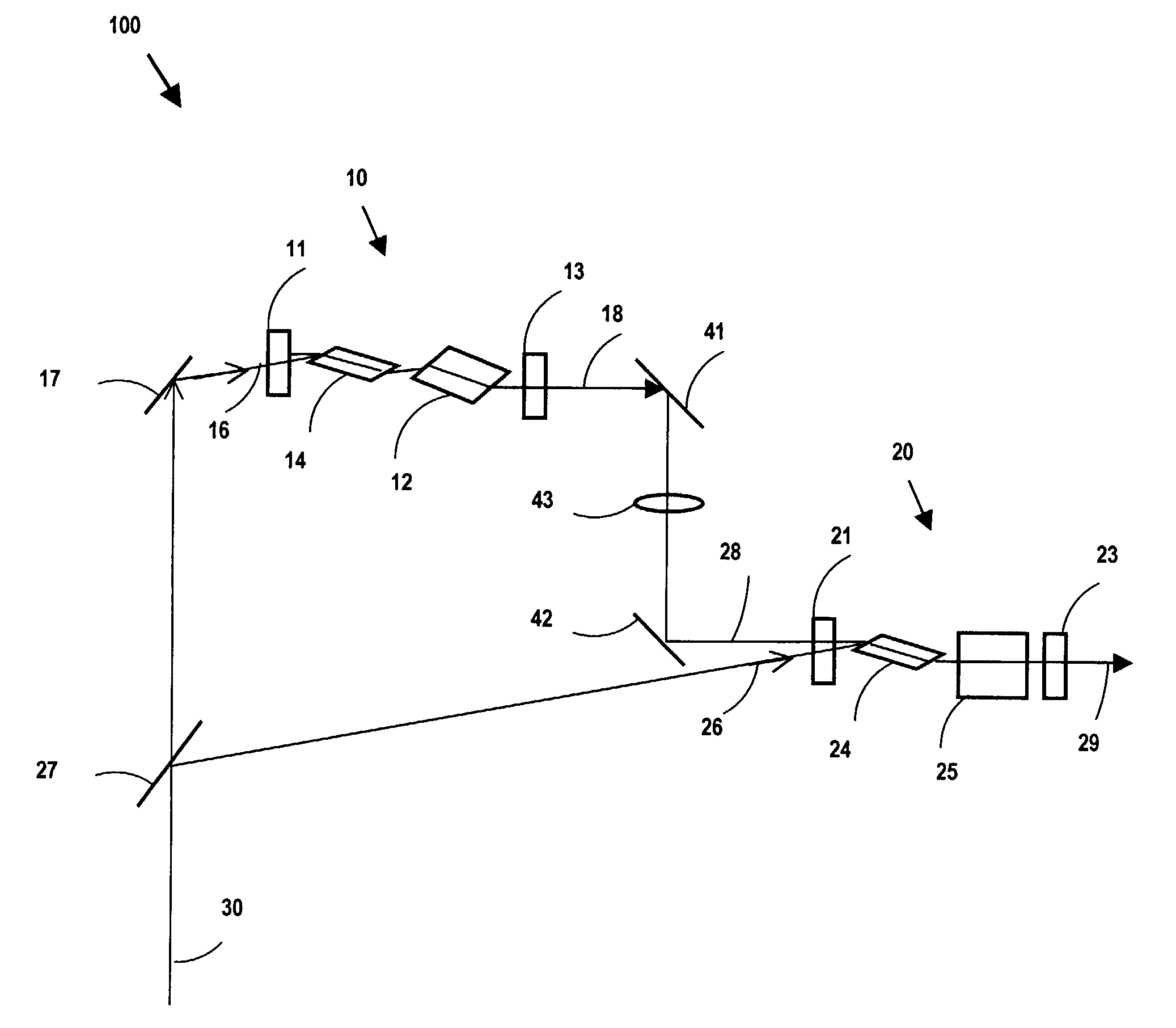
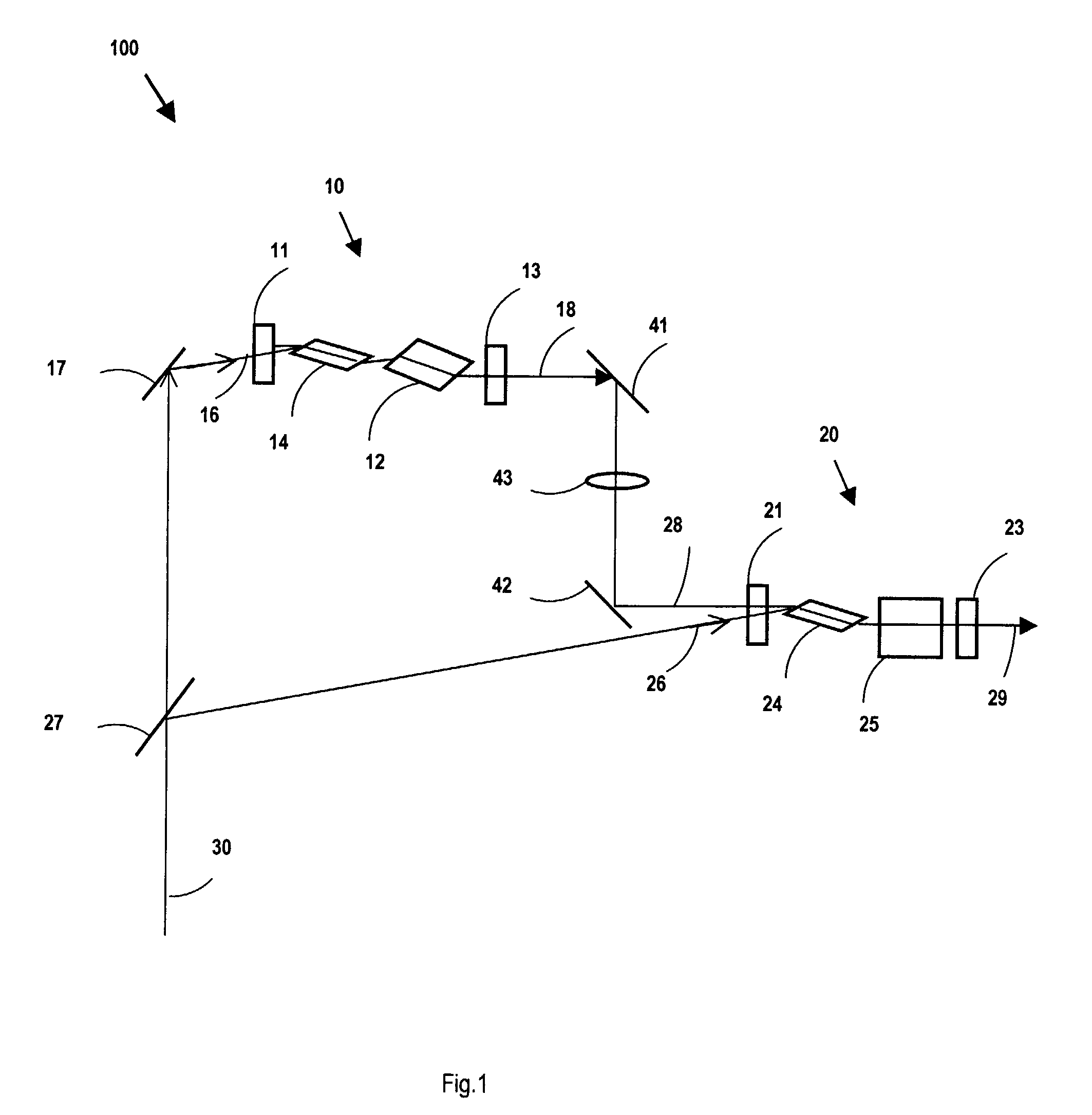
[0018]FIG. 1 is a schematic diagram showing a simplified laser oscillator-amplifier system 100, in accordance with the present invention. The system 100 consists of primarily a laser oscillator 10, a laser amplifier 20, and a pump pulse 30. The system 100 further consists of coupling optics 17, 27, 41, 42, and 43. When excited by a pump pulse 30, the system 100 produces an output pulse 29.

[0019]The laser oscillator 10 consists of a first end mirror 11, a second end mirror 13, a gain medium 14, and a wavelength control element 12. The laser oscillator 10 is designed to operated at low pump threshold and to obtain a seed pulse 18 of narrow bandwidth and long pulse duration. A general guideline for the design of the laser oscillator 10 is low gain, low loss, and short cavity length.

[0020]The first end mirror 11 has a high reflectivity at the laser wavelength and high transmission at the pump pulse wavelength. The second end mirror 13 has a certain transmission at the laser wavelength a...


PUM


Abstract

The present invention contemplates a simplified laser oscillator-amplifier system for deep UV generation. The simplified system employs same type of gain media in both the oscillator and the amplifier and utilizes a single pump pulse split to pump both the oscillator and the amplifier. A short cavity oscillator is operated near lasing threshold to produce a seed pulse with a narrow spectral bandwidth and long pulse duration. A short cavity amplifier is Q-switched to amplify the seed pulse to produce a single short pulse with good energy extraction efficiency. The amplifier is simply a short cavity, Q-switched laser. Short pulse is obtained with short cavity length and high gain of the amplifier. Consequently, the simplified laser oscillator-amplifier system can accommodate a long pump pulse to produce a nanosecond pulse suitable for deep UV laser generation.

Description

FIELD OF THE INVENTION[0001]The present invention relates to a laser system. In particular, the present invention relates to a simplified oscillator-amplifier laser system that is suitable for deep UV generation.BACKGROUND OF THE INVENTION[0002]Solid-state laser sources operated at deep UV wavelength around 200 nm are greatly desirable for photo-refractive surgeries. Such a deep UV laser source is expected to be more compact, more reliable, and require less maintenance in comparison with the excimer lasers, which is currently the dominant laser source for photo-refractive surgeries. More importantly, solid-state laser sources can be operated at a much higher repetition rate and with much less energy fluctuation compared with the excimer lasers. Scanning a deep UV laser beam with high repetition rate enables a variety of ablation shapes on a cornea surface and provides a great flexibility for the refractive surgeries. The improved stability in pulse energy from a solid-state UV laser...

Claims


Application Information

Patent Timeline
Patent Type & Authority Patents(United States)
IPC IPC(8): H01S3/13H01S3/08H01S3/082
CPCH01S3/10092H01S3/094038H01S3/094076H01S3/1625H01S3/115H01S3/1623H01S3/094061
Inventor LAI, MINGQU, ZHIMINMOHEBI, MEHRDAD
Owner LAI MING
Why Eureka
Try Eureka