Corn burner

a burner and corn technology, applied in the field of furnaces, can solve the problems of not being able to reliably control the flow of air through the furnace, not being able to predict the temperature, and not being able to control the size of the kernel, so as to prevent the formation of clinkers, maximize the total capacity of the furnace for a given volume, and efficiently convert a pellet fuel

Inactive Publication Date: 2006-02-28
ANDERSON C MERTON +1
View PDF34 Cites 22 Cited by
  • Summary
  • Abstract
  • Description
  • Claims
  • Application Information

AI Technical Summary

Benefits of technology

[0015]A first object of the invention is to provide thermal energy through the combustion of corn kernels or like fuels. A second object of the invention is to convert a pellet fuel efficiently. Another object of the present invention is to generate a minimum amount of ash and prevent the formation of clinkers. A further object of the invention is to anticipate thermal demand, and adjust thermal output appropriately. Yet another object of the present invention is to distribute combustible fuel throughout a combustion chamber, whereby the total capacity of the furnace for a given volume is maximized.

Problems solved by technology

In spite of ready availability, and often times extremely competitive pricing per unit of energy produced, the use of corn as a fuel source has presented several challenges.
One such challenge is the delivery of the corn kernels to the combustion chamber, hereinafter referred to as the fire pot.
Unfortunately, it is not always possible to control how tightly the kernels may be packed within the auger.
Consequently, it is also not possible to reliably control the flow of air there through, nor to predict the temperature therein.
Another limitation of pellet furnaces in general, and also corn burners, is the difficulty with initial ignition and start-up of the furnace.
Solid pellets or kernels are not readily mixed within an air stream, and so consequently cannot simply be sprayed and ignited with a spark or the like.
Eventually, it is desirable to have as large a region within the fire pot heated as possible, though using the prior art burners this has not been practical.
Unfortunately, this exposes the ignitor to continuously elevated temperatures, which tends to degrade the ignitor unnecessarily.
Furthermore, the physical placement of the ignitor, which is usually selected to be in as close a proximity to the solid fuel as is reasonably practical, will interference once the combustion process has actually begun and attained a self-supporting status.
Nevertheless, the control of these ignitors has heretofore required expensive equipment which has been of little use or benefit other than for the few seconds of use inserting or removing the ignitor.
Consequently, the additional hardware and mechanics that add cost are most undesired.
Another challenge of corn burners is the requirement for proper temperature, mixing and oxygen exposure.
If a mass of corn is left relatively undisturbed during the burning process, there is a great likelihood that a clinker will form.
Unfortunately, owing to the hardness and solid mass formed, a clinker will not typically further burn, and it will instead interfere with the combustion of other kernels.
Finally, the presence of these clinkers represents a waste product which is undesirable, and will require further disposal.
Yet another challenge of the prior art pellet and corn burners is that of maintaining optimum temperature control.
Furthermore, the start-up of a corn burner is less precise and may require user intervention.
Both the time and intervention required will interfere with or prevent the cycling found in liquid or gas furnaces.
In the past, this control has either been absent, meaning the furnace has been simply run at full capacity non-stop, or there has been only limited control provided.
However, when a larger door, such as an overhead door commonplace in factory loading docks and where large machinery is stored and removed for use, there may be substantial heat loss in short time periods.
The present thermal regulation of corn burners is inadequate to compensate for these short period loads.

Method used


Image

  • Corn burner
  • Corn burner
  • Corn burner

Examples


Embodiment Construction

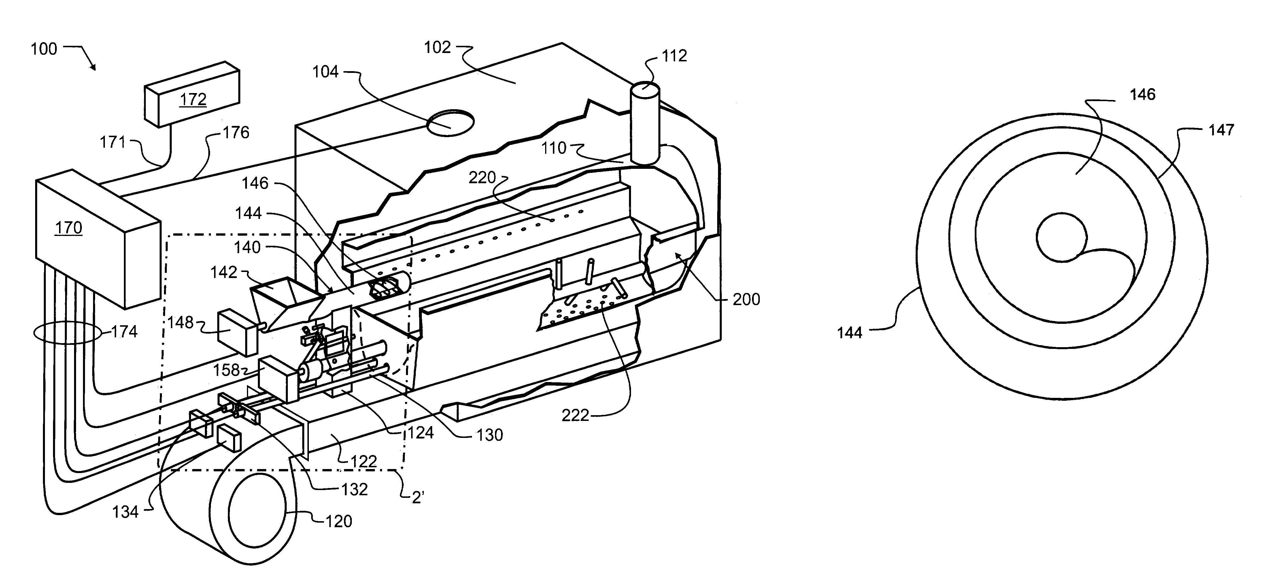
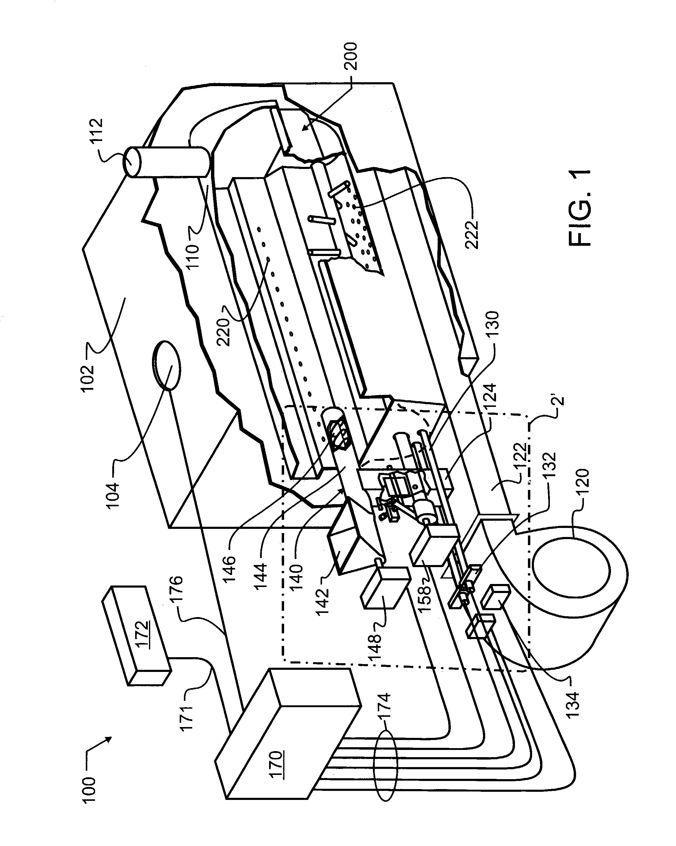
[0025]A most preferred embodiment corn burner 100 designed in accord with the teachings of the present invention is illustrated in FIG. 1. A fire chamber wall formed by cover 110 and fire pot 200 isolates combustion gases from an exterior thereof, while providing a compartment within which safe and controlled burning may occur. Passing through the fire chamber wall is an exhaust 112, which most preferably encloses and directs combustion gases to a safe exterior vent. The overall efficiency of corn burner 100 may be improved from the schematic illustration of FIG. 1 if, for example, the exhaust is brought through the interior of furnace exterior wall 102, such as, for example, by adding two right angle bends therein which would run exhaust 112 parallel to fire pot 200. This provides more surface area for heat to be exchanged through from an exhaust gas stream and the room air being heated.

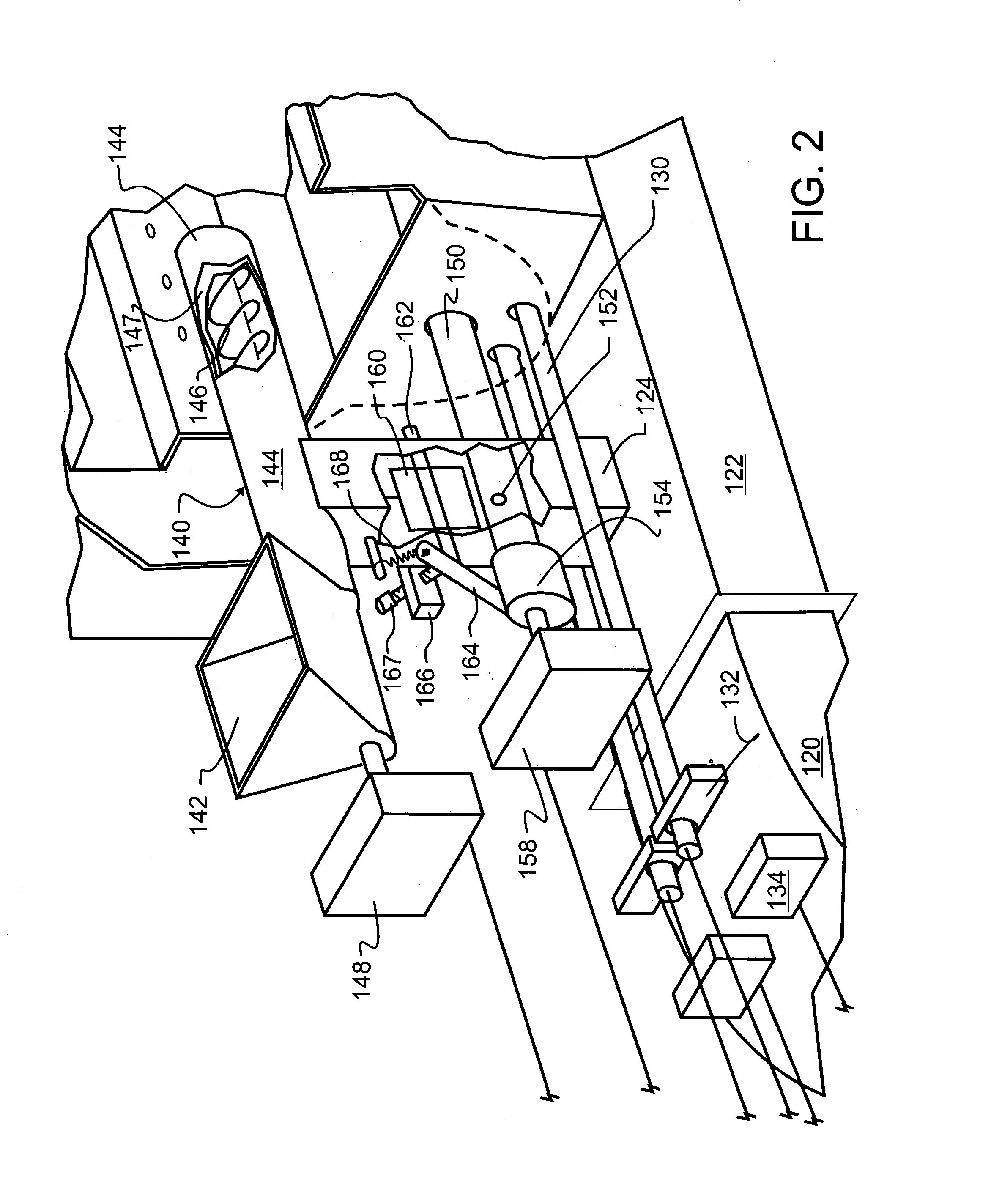
[0026]Auger 140, through outer auger tube 144, also passes through the fire chamber wall. Auger ...


PUM


Abstract

A corn-burning stove provides cooling for the corn in-feed auger and other adjacent components by combustion inlet air flow patterns. The inlet air flow transports pellet fuel through a distance within the fire pot which varies responsive to the flow rate of the inlet air flow. A fire pot and agitator ensure, in combination with the inlet air flow, complete burning of the corn, with almost no ash production and while avoiding the formation of clinkers. The agitator is toothed, having teeth closely adjacent the burn pot for moving burning corn kernels or solid pellets across the fire pot. Retractable ignitors have handles and furnace function interlocks. A process control is associated with the corn burner that includes some logic, including interlock, power control, speed controls, sensing inputs/devices, and user interface.

Description

CROSS REFERENCE TO RELATED APPLICATIONS[0001]This application claims priority to U.S. provisional patent application Ser. No. 60 / 401,281 filed Aug. 5, 2002.BACKGROUND OF THE INVENTION[0002]1. Field of the Invention[0003]This invention pertains generally to furnaces, and more particularly to furnaces that incorporate screw-type fuel feeders. In a particular manifestation of the invention, corn kernels are used as a fuel source.[0004]2. Description of the Related Art[0005]Thermal energy has many fundamental applications, ranging from basic necessities such as adequate warmth within a shelter to comfort and pleasantries such as hot water used in baths, spas and swimming pools. Representative of the breadth of applications are the diverse apparatus that have been devised to provide desired thermal energy. Common modern sources of thermal energy include electricity such as is typically produced at large electrical generation power plants, propane, kerosene, fuel oil, other petroleum-deri...

Claims


Application Information

Patent Timeline
Patent Type & Authority Patents(United States)
IPC IPC(8): F23G5/00F23G5/44F23N5/18
CPCF23B30/00F23B40/00F23G5/444F23G5/50F23N1/022F23G2205/121F23G2209/26F23G2900/50206F23G2201/90
Inventor ANDERSON, C. MERTONANDERSON, CHARLES LYNN
Owner ANDERSON C MERTON
Why Eureka
Try Eureka