Vibration absorber assembly

a technology of vibration absorber and assembly, which is applied in the direction of shock absorbers, mechanical control devices, instruments, etc., can solve the problems of excessive wear of bearings, excessive wear of clutch plates, and breakage of components, so as to reduce the weight of reduce the weight of the flywheel and/or vibration dampener, and efficiently absorb torsional vibration and/or alter the moment of inertia of the device

Inactive Publication Date: 2006-02-28
WILLIAMS KENNETH A
View PDF13 Cites 25 Cited by
  • Summary
  • Abstract
  • Description
  • Claims
  • Application Information

AI Technical Summary

Benefits of technology

[0018]Another advantage of the present invention is in providing a vibration absorber and method that more efficiently absorbs torsional vibration and/or alters moment of inertia of the device.
[0019]Still another advantage of the present invention is in providing a vibration absorber and method that improves the output and efficiency of the engine.
[0020]Yet another advantage of the present invention is in reducing the weight of the flywheel and/or vibration dampener and drive train parts in comparison to such components providing similar performance.
[0021]In accordance with one embodiment of the present invention, vibration absorber assembly is provided, the vibration absorber including a disc shaped housing having a central rotational axis and a plurality of radially elongated cavities, and a plurality of movable masses, each movable mass being housed in, and movable within, one of the plurality of radially elongated cavities. In this regard, the plurality of movable masses are preferably movable in the plurality of radially elongated cavities to absorb torsional vibration,

Problems solved by technology

The power delivered to the crankshaft or output shaft is inconsistent and varies at most of the individual 360 degree points that comprise a single revolution in terms of its components, including torque magnitude and rotation speed.
These peaks and valleys in torque output result in excessive wear to bearings, gears, clutch plates, universal joints, breakage of component parts such as camshafts, crankshafts, etc., as well as a reduction in power output, and increased fuel consumption.
Because the mass is not fixed, a damper exhibits a dampening or shock absorbing effect upon the torsional vibration of the output shaft, while wasting some of the excess horsepower as heat.
In addition, because of the mass of the vibration damper, the vibration damper also acts like a flywheel except that a time delay in response occurs since the mass is not fixed.
These high deviations from no

Method used


Image

  • Vibration absorber assembly
  • Vibration absorber assembly
  • Vibration absorber assembly

Examples


Embodiment Construction

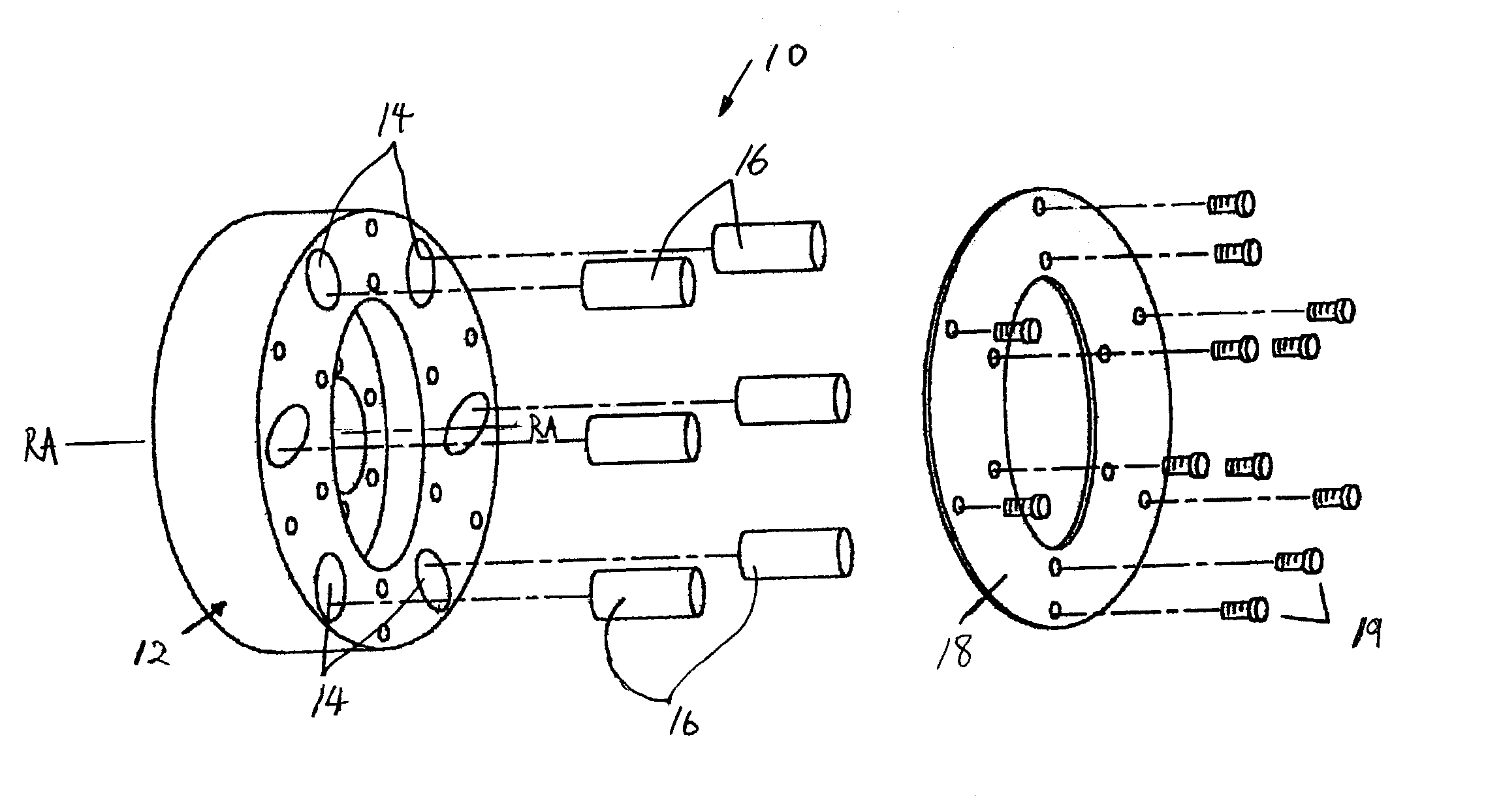
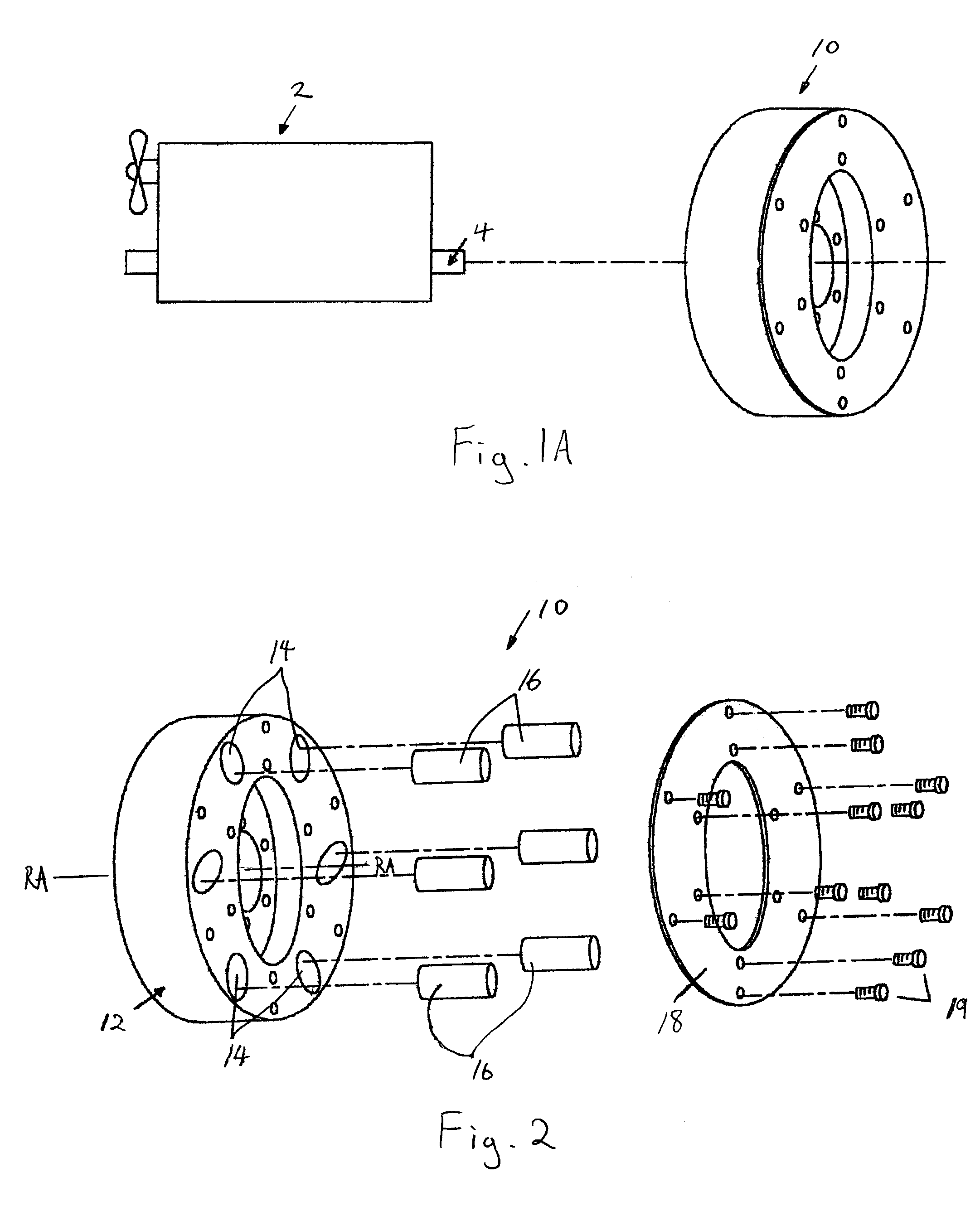
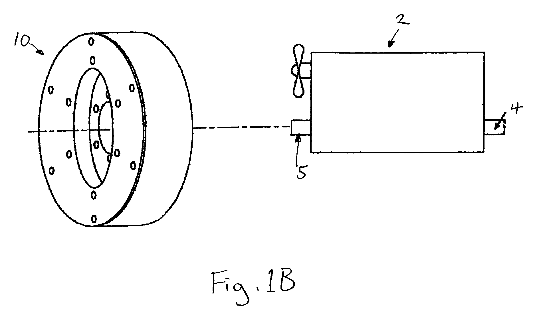
[0051]FIG. 1A shows a vibration absorber assembly 10 in accordance with one embodiment of the present invention which is used as a flywheel to absorb torsional vibration generated by various devices such as an internal combustion engine 2. In this regard, the vibration absorber assembly 10 may be designed for attachment to the output shaft 4 of the internal combustion engine 2 for use as the flywheel. Of course, the vibration absorber assembly 10 is not drawn to scale in FIG. 1A. Alternatively, as shown in FIG. 1B, the vibration absorber assembly 10 may be designed for attachment to the front 5 of the crank shaft of the internal combustion engine 2, and be used as a vibration dampener which is also commonly referred to as a harmonic balancer. Again, FIG. 1B is not to scale. Of course, the vibration absorber assembly 10 may be appropriately modified for intended use, whether it be used as a flywheel or a vibration dampener.

[0052]Regardless of where the vibration absorber assembly 10 ...


PUM


Abstract

A vibration absorber assembly including a disc shaped housing having a central rotational axis and a plurality of radially elongated cavities, and a plurality of movable masses, each movable mass being housed in, and movable within, one of the plurality of radially elongated cavities. The plurality of movable masses are movable in the plurality of radially elongated cavities to absorb torsional vibration, and/or alter moment of inertia of the vibration absorber assembly.

Description

BACKGROUND OF THE INVENTION[0001]1. Field of the Invention[0002]This invention relates to an improved vibration absorber for internal combustion engines. More specifically, this invention is directed to an improved vibration absorber assembly for absorbing torsional vibration and altering the moment of inertia of the vibration absorber assembly.[0003]2. Description of Related Art[0004]Internal combustion engines utilize one or more cylinders that operate in a combustion cycle and fire sequentially in order to provide torque to a crankshaft or other output shaft thereby causing rotation thereof to provide power. This power is then used by cars, trucks, boats, generators, pumps, etc.[0005]The power delivered to the crankshaft or output shaft is inconsistent and varies at most of the individual 360 degree points that comprise a single revolution in terms of its components, including torque magnitude and rotation speed. It is not unusual for the torque to deviate from nominal torque by ...

Claims


Application Information

Patent Timeline
IPC IPC(8): F16F7/10F16F15/14F16F15/31
CPCF16F15/145F16F15/31Y10T74/2128Y10T74/2111
Inventor WILLIAMS, KENNETH A.
Owner WILLIAMS KENNETH A
Why Eureka
Try Eureka