Light source device

a technology of light source and light guide, which is applied in the direction of lighting and heating equipment, instruments, machines/engines, etc., can solve the problems of uniform luminance in the light output surface, inability to obtain a good display screen, and difficulty in weight reduction or thinning of the back surface light source device of direct-under lighting system, etc., to achieve the effect of increasing the distance from the primary light source and reducing the thickness of the light guid

Inactive Publication Date: 2006-02-28
MITSUBISHI RAYON CO LTD
View PDF25 Cites 152 Cited by
  • Summary
  • Abstract
  • Description
  • Claims
  • Application Information

AI Technical Summary

Benefits of technology

[0039]In an aspect of the present invention, a thickness of the light guide is reduced as a distance from the primary light source is increased.

Problems solved by technology

The back surface light source device of the direct-under lighting system has had a difficulty of weight-reducing or thinning of a light source portion, and a problem of easy occurrence of a see-through phenomenon where the fluorescent lamp or the like used as a primary light source is seen through from a sign board.
Consequently, luminance in the light output surface becomes non-uniform, making it impossible to obtain a good display screen.
Such a tendency becomes conspicuous as the surface light source device is enlarged, and cannot endure practical use in a surface light source device of 10 inches or more.
In such surface light source devices, there is a drawback that use of a white pigment of titanium oxide, barium sulfate or the like as a light scattering material causes a light loss such as light absorption when a light incident on the light scattering material is scattered, leading to a reduction in luminance of an outputted light in a desired direction.
In such surface light source devices, however, there is also a drawback that impossibility of reuse of a light reflected by the outputted light adjustment member or the light diffusion plate causes a light loss, leading to a reduction in luminance of an outputted light in a desired direction.
Such a surface light source device can obtain very high luminance, but it is not satisfactory in uniformity of luminance in the light output surface.
However, there is still a problem in subtle reproducibility of the mat finished surface configuration.
Additionally, in such a surface light source device, because a distribution of an outputted light (distribution in directions vertical and parallel to light input surface) is too wide (especially in the direction parallel to light input surface), as a surface light source device used for a portable electronic device, requirements of low power consumption and high luminance cannot be satisfied.
However, as the light guide is made thinner and a ratio of a length to its thickness is made larger, it is difficult to obtain uniform output characteristics of a light in the light output surface only by a structure where the surface is constituted of many substantially spherical minute convex bodies.
On the other hand, a uniformity ratio of an outputted light luminance distribution tends to be lost greatly.
As in the case of this method, it is very difficult to obtain a high uniformity ratio of luminance based on formation of many micro concave and convex portions by a mat finished surface or other dot patterns, a distribution of shapes thereof or the like to add a special function to the light guide itself.
Thus, it has been a great technical problem to simultaneously obtain a high uniformity ratio without losing the special functionality added to the light guide itself.
However, since a light traveling in a direction oblique to the elongated prism cannot be directed to the normal direction of the light output surface, the amount of this light becomes a loss.
Thus, especially the surface light source device using the point light source has had a problem in terms of light use efficiency.
In these surface light source devices, however, there is a problem that because of a wide distribution of an outputted light, luminance per power consumption cannot be sufficiently increased and, because of a spot shape of a light source, only a portion before the light source is bright, causing uneven luminance as a whole.
However, in such a surface light source device, there is a problem that because of the discrete arrangement of the triangular convex shape portions, a light propagated through the light guide cannot be efficiently outputted in the normal direction of a light output surface.

Method used


Image

  • Light source device
  • Light source device
  • Light source device

Examples


example 1

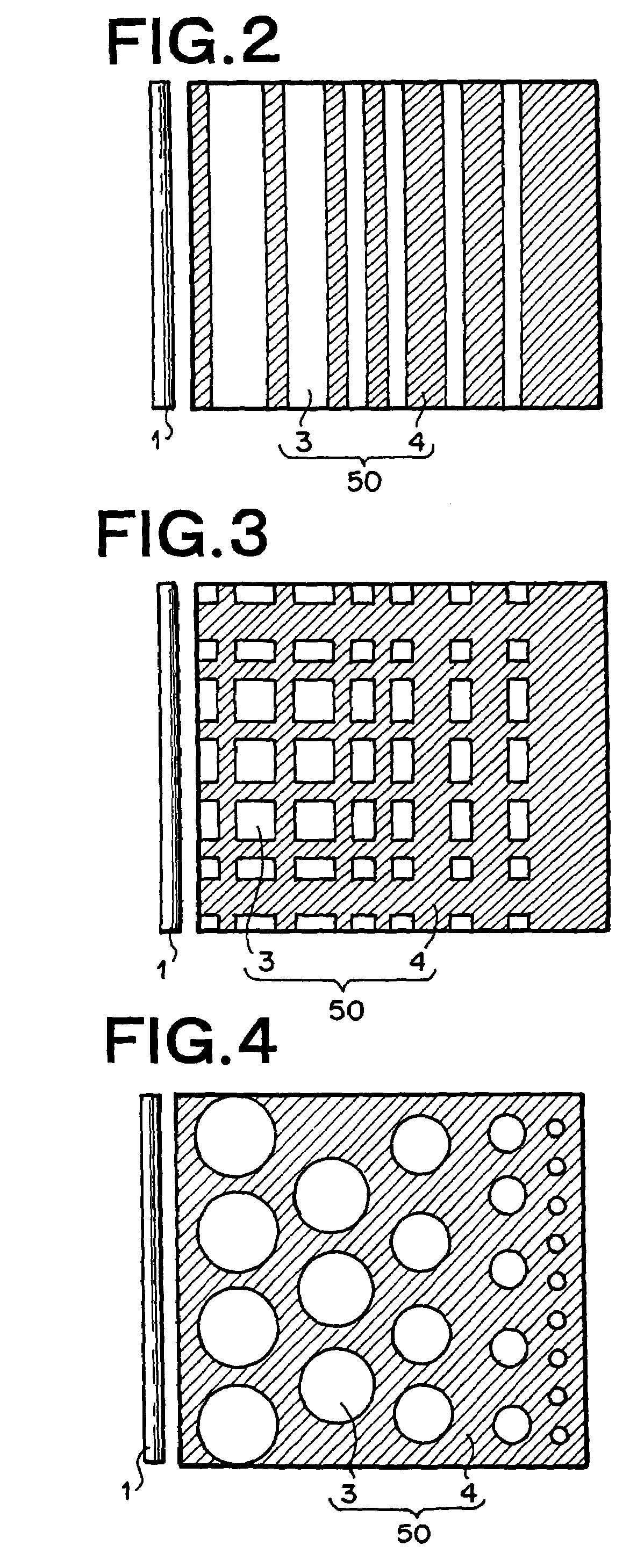
[0179]By the manufacturing method described above with reference to FIGS. 14 and 15, a surface light source device comprising a light leakage modulator having a light diffusion function was manufactured. A mat finished structure was employed for a light diffusion function layer 42 and, regarding a metal mold for transferring the mat finished structure, glass beads having a diameter of 50 to 90 μm were blasted to a SUS plate to form a concave and convex configuration. Then, the mold was wound around a roll to form a roll mold. On the other hand, a circular form similar to that shown in FIG. 4 was employed for a low refractive index region 3 of a composite layer 50 for controlling a light leakage distribution from a light guide 6 to the layer 42 of the mat finished surface, and an air layer (refractive index of 1.000) was employed for the low refractive index region 3. However, a diameter of each circular low refractive index region 3 was set to 60 μm, and a light leakage intensity di...

example 2

[0183]A light leakage modulator was manufactured by using a roll transfer mold to perform UV-curing of ultraviolet curable resin compositions on both surfaces of a polyester film based on the same method as that of the example 1, and a surface light source device having an elongated prism 28 similar to that shown in FIG. 9 was manufactured. That is, in place of the mat finished structure function layer 42 of the example 1, a function layer was used including continuous elongated prisms, where many elongated prisms 28 each having first and second prism surfaces 28a, 28b extending in a direction substantially parallel to a light input surface of a light guide were continuously arrayed in a direction substantially orthogonal to the light input surface of the light guide. An inclination angle of the first prism surface 28a of the elongated prism 28 was 45°, and that of the second elongated prism was 85°. For a size of the surface light source, a length in a direction along a first prima...

example 3

[0185]A surface light source device having narrow visual field characteristics similar to those of the example 2 was manufactured. However, a length of the surface light source device in a direction along a primary light source 1 was 30 mm, a length in a direction orthogonal to the primary light source was 40 mm, and a thickness was 1 mm. Six LED's were used in place of the cold-cathode tube for the light guide of the example 2, and these were arranged adjacently to a light input end surface of a light guide equally at intervals of 5 mm.

[0186]An outputted light luminance distribution (output angle distribution) of the surface light source device was measured. A width of output angles (angular half value width) having luminance value of half the front luminance was about 23° in a direction vertical to the light input surface of the light guide, and thus narrow visual field characteristics were exhibited. Moreover, a ratio of a minimum luminance value / maximum luminance value regarding...


PUM


Abstract

The index of refraction of a light guide (6) for transmitting light outputted from a primary light source (1) is ng, and the light guide (6) has a light input end face (9), a light output surface from which the transmitted light is outputted, and a back surface opposed to the light output surface. A leaky ray modulator (8) is provided to at least either the light output surface or the back surface. The leaky ray modulator (8) has a composite layer (50) provided on the light output surface or the back surface and composed of first refractive index regions (3) having a refractive index n1 (ng>n1) and second refractive index regions (4) having a refractive index n2 (n2>n1) and a third refractive index layer (5) provided on the composite layer (50) and having a refractive index n3 (n3>n1). A reflecting plate (7) is provided adjacent to the back surface of the light guide (6).

Description

TECHNICAL FIELD[0001]The present invention relates to a light source device such as (1) a surface light source device or planar light source device used for a liquid crystal display device used for a notebook computer, a liquid crystal television or the like, and an indication device for guide sign boards and large billboards at stations and public facilities, and traffic guide boards, traffic signs or the like on highways or general roads, (2) a surface light source device or planar light source device using a point light source such as an LED, which is used for a relatively compact liquid crystal display device or the like used for a portable telephone (cellular phone) or a portable information terminal (personal digital assistant [PDA]), and (3) a linear light source device or bar-like light source device for converting a light source of the LED or the like into a uniform linear light source. More specifically, the invention relates to a light source such as a surface light sourc...

Claims


Application Information

Patent Timeline
Patent Type & Authority Patents(United States)
IPC IPC(8): F21V7/04F21V8/00
CPCG02B6/0021G02B6/0028G02B6/0068G02B6/0046G02B6/0065G02B6/0036G02F1/1335
Inventor YAMASHITA, TOMOYOSHIHAYASHI, YASUKO
Owner MITSUBISHI RAYON CO LTD
Why Eureka
Try Eureka