Apparatus for injection molding multilayered articles

a multi-layered, machine-based technology, applied in the direction of dough shaping, applications, manufacturing tools, etc., can solve the problems of high initial cost of the required components and associated control capability, high cost and complexity of a machine requiring two or more independent reciprocating screws, and high cost and complexity of producing a screw with a sufficiently large central bore, etc., to achieve the effect of minor and low-cost changes

Inactive Publication Date: 2006-02-28
COMMUNITY ENTERPRISES
View PDF15 Cites 13 Cited by
  • Summary
  • Abstract
  • Description
  • Claims
  • Application Information

AI Technical Summary

Benefits of technology

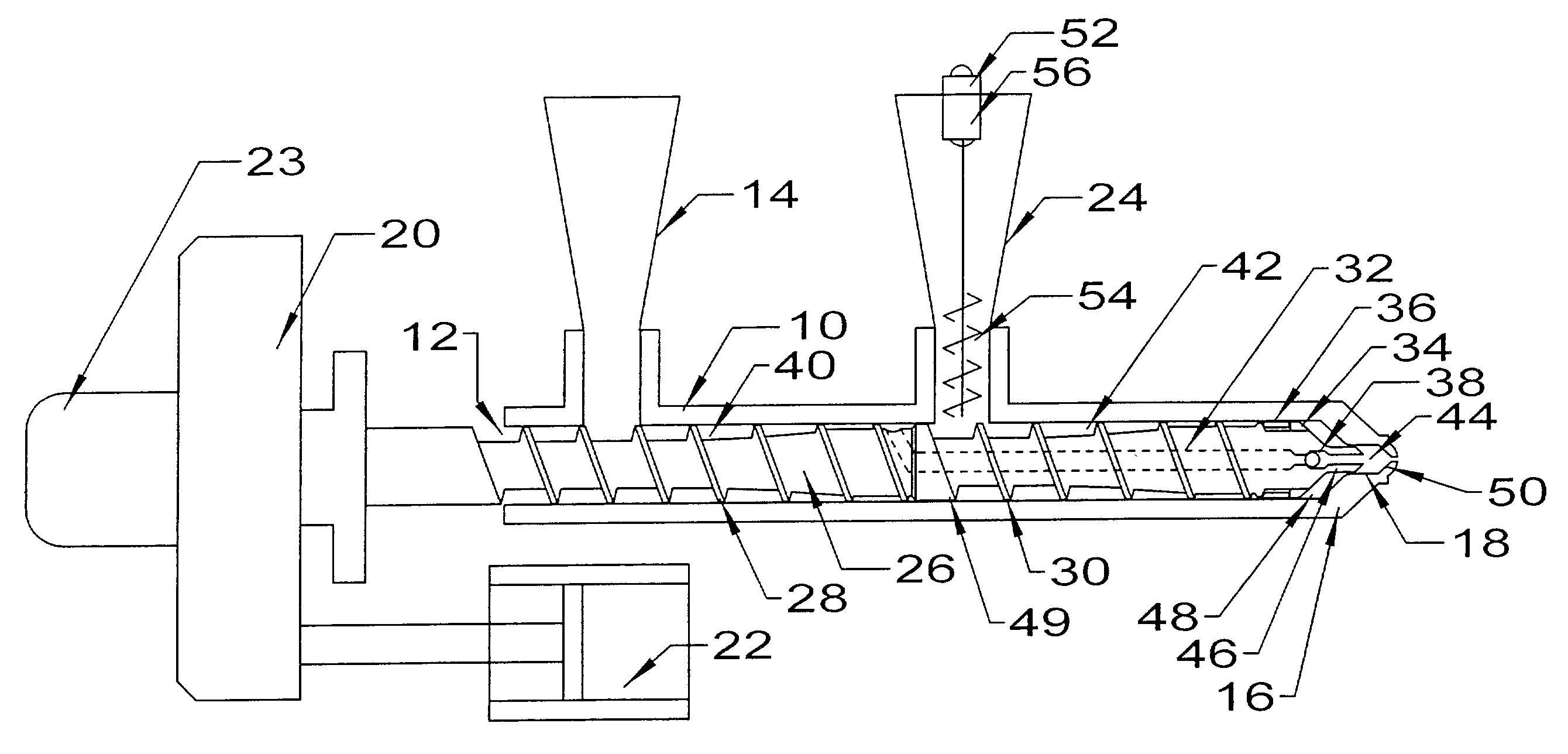
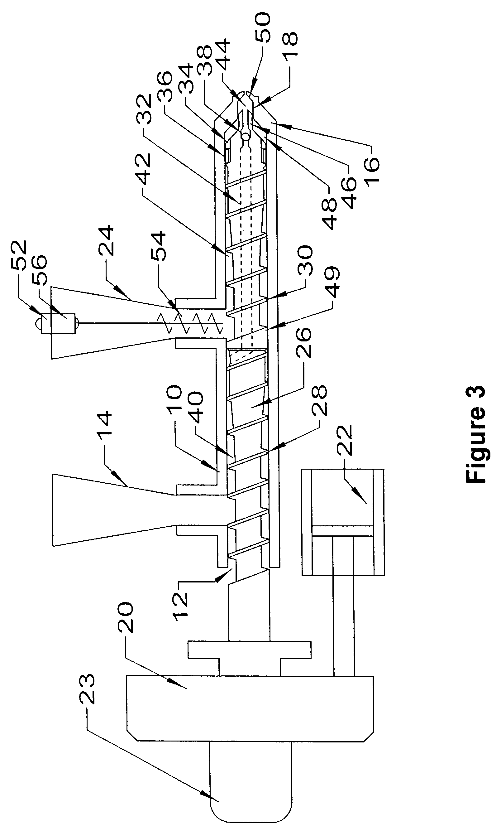
[0006]An object of the present invention is to provide a means whereby the sandwich or coinjection molding process can be performed within the space of a single heated barrel, and furthermore by means of

Problems solved by technology

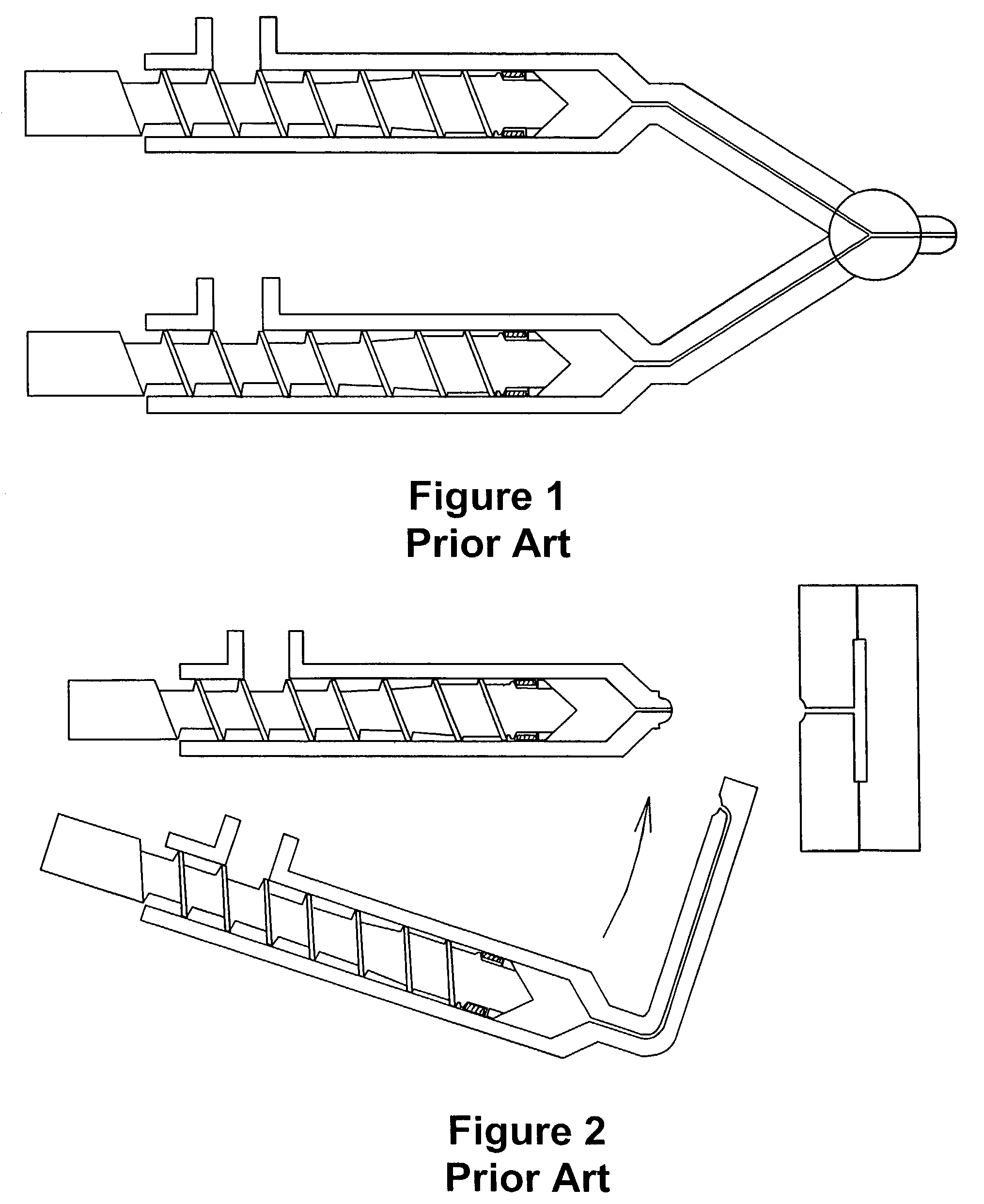
These advantages are offset by the high cost and complexity of a machine requiring two or more independent reciprocating screws, together with the associated controls for simultaneous and/or sequential injection.
Because of the multiple barrels and screw drives, machines of this type still have disadvantages involving the high ini

Method used


Image

  • Apparatus for injection molding multilayered articles
  • Apparatus for injection molding multilayered articles
  • Apparatus for injection molding multilayered articles

Examples


example 1

[0067]An injection molding machine having a 45 millimeter barrel diameter, produced by Ferromatik Milacron of Batavia, Ohio, was fitted with a barrel and screw in accordance with the present invention. A single starve feeder was mounted to the downstream feed throat. Using a variety of molds, multilayer parts having a weight of 12 grams up to 250 grams were produced. In these parts, the inner core layer was varied between 10% and 70% of the total part weight. Thermoplastic materials used successfully included polypropylene, polyethylene, acrylonitrile butadiene styrene, nylon, polyphenylene oxide, acetal, polyvinyl chloride, and polycarbonate.

example 2

[0068]On the machine in Example 1, a second starve feeder was mounted to the upstream feed throat. With the second feeder, parts having a core percentage as high as 95% by weight were produced, with the core material being polypropylene and the skin material being thermoplastic elastomer.

example 3

[0069]The machine in Example 1 was fitted with front end components as shown in FIG. 11. Using a mold with two independent runners feeding different points of a common cavity, parts were produced having regions composed throughout of two different materials, rather than of a sandwich structure.


PUM

PropertyMeasurementUnit
Timeaaaaaaaaaa
Temperatureaaaaaaaaaa
Lengthaaaaaaaaaa

Abstract

An apparatus for injection molding two compatible polymeric materials, in which two or more plasticizing zones on a screw are used to simultaneously or sequentially plasticize the two materials into a common accumulation space through separate pathways. The charge comprising multiple layers of material is then injected into a closed mold by means of forward axial motion of the screw with respect to its enclosing barrel. Once inside the mold, the first material forms a skin layer, totally or partially surrounding the other material. In this way a part having a plurality of material properties may be produced in a single operation.

Description

CROSS REFERENCE TO RELATED APPLICATIONS[0001]This application claims the benefit of U.S. Provisional Application No. 60 / 330,397 filed Oct. 18, 2001.BACKGROUND OF THE INVENTION[0002]The most common commercial form of injection molding machine is known as a “reciprocating screw”. In this type of machine, thermoplastic polymer is melted, mixed, and conveyed by means of a screw having one or more flights rotating within a heated pressure vessel. The screw is also permitted to translate axially to allow for the accumulation of melted material at the end of the screw. When sufficient melt has accumulated, the screw is stopped and translated forward to inject the melted material into a closed mold. In common practice a non-return valve is situated at the downstream end of the screw to prevent back flow into the screw flights during the injection portion of the cycle.[0003]A variation of this process, known as co-injection or sandwich molding, has been commercially practiced for a number of...

Claims


Application Information

Patent Timeline
IPC IPC(8): B29C47/04B29C45/50B29C48/00B29C45/16B29C45/52B29C45/60B29C45/74B29C48/51B29C48/605
CPCB29C45/1645B29C45/1866B29C45/60B29K2077/00B29C45/52B29C45/581B29C45/62B29C45/74B29C47/0009B29C47/60B29C47/6006B29C47/6075B29C49/04B29C49/06B29K2023/06B29K2023/12B29K2027/06B29K2055/02B29K2069/00B29C45/1808B29C48/03B29C48/51B29C48/605B29C2949/0715B29C45/16
Inventor THOMSON, JOEL
Owner COMMUNITY ENTERPRISES
Why Eureka
Try Eureka