Check patentability & draft patents in minutes with Patsnap Eureka AI!

Hot isostatic pressing apparatus and hot isostatic pressing method

a pressing apparatus and hot isostatic technology, applied in lighting and heating apparatus, furnaces, muffle furnaces, etc., can solve the problems of increasing the treatment cost, reducing the cycle time, and excessive heat dissipation, and achieve excellent temperature uniformity, long treatment cycle time, and improved cooling rate

Active Publication Date: 2006-03-14
KOBE STEEL LTD
View PDF8 Cites 21 Cited by
  • Summary
  • Abstract
  • Description
  • Claims
  • Application Information

AI Technical Summary

Benefits of technology

[0012]The present invention has been achieved to solve the problems of conventional techniques as described above. Namely, the present invention has an object to provide a hot isostatic pressing apparatus (HIP apparatus) and hot isostatic pressing method (HIP method) capable of efficiently cooling workpieces to a temperature range of 100° C. or lower which allows a quenching treatment and safe manual handling of workpieces.

Problems solved by technology

Further, the natural convection of the gas also causes the excessive dissipation of the heat for heating the treatment chamber 52.
As is apparent from FIG. 8, the long overall treatment time, particularly, the long residence time of workpieces in the expensive high-pressure vessel results in an increase in treatment cost, and a reduction in the cycle time has been thus a serious subject in industrial productions.
Consequently, the problem that the thermal histories of workpieces in the treatment chamber are varied depending on places became to be recognized.
However, an uniform circulating gas flow cannot be obtained because the pump for forcedly circulating the gas in the inside and outside spaces of the heat insulating hood is positioned closer to one side of a lower lid.
Further, uniform cooling of the circulating gas cannot be expected because the heat exchanger is also shifted in conformation to the setting position of the pump.
Therefore, the problem that the thermal histories of the workpieces in the treatment chamber are varied depending on places is supposed.
However, the limitation of temperature (substantially a surface temperature of 100 to 150° C.) in the high-pressure vessel as heat sink (temperature lowering device) still remains even with the above method, and it is the actual condition that a sufficient function cannot be necessarily provided in the point of cooling to 100° C. or lower.

Method used


Image

  • Hot isostatic pressing apparatus and hot isostatic pressing method
  • Hot isostatic pressing apparatus and hot isostatic pressing method
  • Hot isostatic pressing apparatus and hot isostatic pressing method

Examples


Embodiment Construction

[0038]The present invention will further be described in detail in reference to the drawings of preferred embodiments of the present invention.

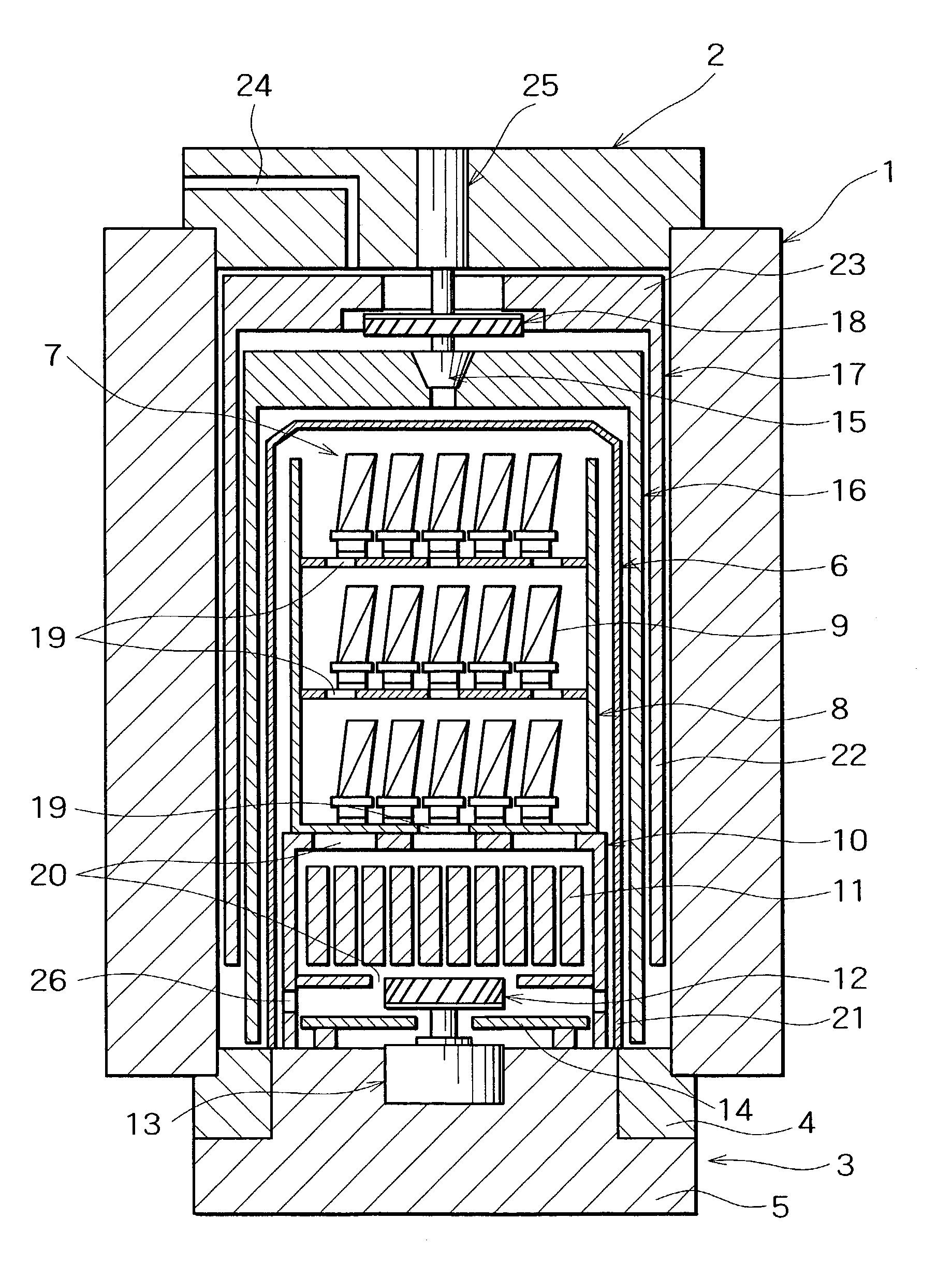
[0039]FIG. 1 is a schematic sectional view of a HIP apparatus according to the present invention. A bottomed cylindrical casing 6 (reversed tumbler-shape casing) is arranged on the inside of a high-pressure vessel comprising a high-pressure cylinder 1, an upper lid 2 and a lower lid 3, and a treatment chamber 7 is formed in the inner part thereof. A workpiece case 8 having a hole 19 formed so as to facilitate the flowing of a gas is arranged in the treatment chamber 7, and workpieces 9 are arranged therein. The workpiece case 8 is placed on a workpiece base 10 having holes 20 for passing the gas. A heater 11, a pressure medium gas stirring fan 12, and a heat insulating plate 14 for cutting off the transfer of heat to a motor 13 for driving the pressure medium gas stirring fan 12 are housed in the workpiece base 10.

[0040]The casing 6 comprises...


PUM

PropertyMeasurementUnit
Temperatureaaaaaaaaaa
Pressureaaaaaaaaaa

Abstract

A hot isostatic pressing apparatus (HIP apparatus) comprises a vertically cylindrical high-pressure vessel comprising a high-pressure cylinder 1 and upper and lower lids 2 and 3; a bottomed cylindrical casing 6 capable of housing workpieces 9 and a resistance-wire heater 11, a heat insulating structure 16 equipped with a gas flow regulating valve 15 and formed in a bottomed cylindrical shape on the outside of the casing 6 so as to cover the casing 6, and a heat sink 17 having a water cooling mechanism provided in the space defined by the heat insulating structure 16 and the inner surface of the high-pressure cylinder 1, which are provided within the high-pressure vessel; and a pressure medium gas stirring fan 12 for promoting the temperature uniformity of the space of the treatment chamber 7 for housing the workpieces 9, the stirring fan being arranged on the lower lid 3 side within the casing 6, whereby the cooling to a temperature range of 100° C. or lower which allows a quenching treatment and the safe manual handling of workpieces can be efficiently performed.

Description

BACKGROUND OF THE INVENTION[0001]1. Field of the Invention[0002]The present invention relates to a hot isostatic pressing apparatus and a hot isostatic pressing method.[0003]2. Description of the Related Art and Problems to be Solved by the Invention[0004]As a technique for eliminating residual pores in casting products or in sintered products such as ceramics by performing a heat-up under a high-pressure gas atmosphere of several tens to several hundreds MPa, hot isostatic pressing (HIP) has been extensively used in industrial fields with confirmation of effects such as improvement in mechanical characteristic, reduction in scatter of properties, and improvement in yield.[0005]A conventional HIP apparatus used for the purpose as described above has, as shown in FIG. 7, a structure containing a so-called resistance-wire heating electric furnace, in which a bottomed cylindrical heat insulating structure 44 and a resistance-wire heater 45 arranged along the inner surface of the heat i...

Claims


Application Information

Patent Timeline
IPC IPC(8): B29C43/10B22F3/15B30B5/02B29C43/00B29C43/52B29C43/58F27B5/04F27B5/14F27B5/16F27B17/00
CPCB22F3/15B29C43/006B29C43/10B30B11/002F27B5/04B22F3/003Y10S425/815B29C43/52B29C43/58F27B5/14F27B2005/162F27B2005/167B22F2999/00
Inventor NAKAI, TOMOMITSUYONEDA, MAKOTOKOFUNE, SHIGEOFUJIKAWA, TAKAO
Owner KOBE STEEL LTD
Features
  • R&D
  • Intellectual Property
  • Life Sciences
  • Materials
  • Tech Scout
  • Unparalleled Data Quality
  • Higher Quality Content
  • 60% Fewer Hallucinations
Learn More