Electrodes for alkaline fuel cells with circulating electrolyte

a fuel cell and electrolyte technology, applied in the direction of cell components, electrolyte stream management, electrochemical generators, etc., can solve the problems of high rejection rate, low flexibility, and high damage to electrodes, and achieve the effect of reducing the number of defective or rejected electrodes, dimensionally stable and highly flexible porous electrodes, and reducing the incidence of damage to electrodes during manufactur

Inactive Publication Date: 2006-03-21
APOLLO ENERGY SYSTEMS +4
View PDF6 Cites 21 Cited by
  • Summary
  • Abstract
  • Description
  • Claims
  • Application Information

AI Technical Summary

Benefits of technology

[0042]A major advantage of the present invention is that a dimensionally stable and highly flexible porous electrode is obtained. The incidence of damage to the electrode on handling during manufacture is therefore minimized thus reducing the number of faulty or rejected electrodes, and consequently the cost is reduced. Furthermore, the intrinsic material cost is significantly reduced over carbon paper or woven cloths. In addition, the electrode of the invention is more amenable to high volume continuous production processes due to its high dimensional stability.
[0043]Another advantage of cells fitted with the porous electrodes is their capability to be used not only in continuous mode but also wherever intermediate operation of the cell is necessary. As the cells perform well from −10° C. to +80° C., a startup at ambient temperature is always possible. If the cell construction allows the liquid alkaline electrolyte to leave the cell after being shut down, the overall lifetime of the electrodes gets much higher because corrosion occurs mainly when the cell is left at open circuit without load. If the electrolyte is removed when the cell is not in use, only the hours of operation are counted. The predicted operation time of an alkaline fuel cell electrode is approx. 4000 hours.
[0044]A further advantage of the porous electrodes of the present invention is improved performance due to reduced mass transport losses. During operation of an alkaline fuel cell, product water is produced at the anode. This has to be efficiently removed from the electrode structure so that it does not build up in the structure and impede further diffusion (mass transport) to the reaction sites. With conventional electrodes this is not possible to fully achieve, and it becomes difficult to operate the cell efficiently at higher current densities, which is a desirable goal to improve power density. Porous electrodes of the present invention are suitable for low cost manufacture. The electrodes may be manufactured by one of two general methods.
[0045]The electrodes may be manufactured by taking a pre-formed nickel foam material and applying the catalyst layers comprising the catalyst on carbon and polymeric materials. This can be done by any number of coating processes such as printing, rolling, K-bar or doctor blade methods or spraying.
[0046]A second method for the manufacture of the electrode of the present invention and which provides a further aspect of the present invention, comprises mixing the carbon with at least one catalyst component or a polymeric substance and thereafter forming the porous electrode by adapting a continuous manufacturing process, for example paper-making, calendering or extrusion. For example, in a process based on paper-making technology, the materials are dispersed in a liquid carrier with at least one catalyst component and a polymeric substance to form a dilute slurry and thereafter forming a continuous structure by the controlled deposition of said slurry onto a moving mesh bed, de-watering of the solids and drying and compaction of the nickel foam containing the layers under a suitable time-pressure and temperature regime.
[0047]The paint spraying method is another major advantage because a porous electrode is easily manufactured in a fewer number of steps using continuous manufacturing techniques, thus making it more cost effective and commercially viable. For example, the liquid, carbon and binder containing suspensions can be sprayed on a previously prepared layer of the electrode. Another example is the catalyzation of a finished electrode by spraying solutions of i.e. noble metal salts on a electrode surface.

Problems solved by technology

A major problem with conventional electrodes based on semi-solid porous carbon substrates is the lack of flexibility.
The conventional electrodes are consequently easily damaged on handling which leads to high reject rates during manufactoring of the electrode.
This obviously has an impact on cost.
With conventional porous electrodes based on woven cloth substrates a problem concerns the lack of good dimensional stability, as the cloth can easily be stretched in the directions of the major planar faces (x and y directions).
This can make the manufacturing of electrodes using these substrates very difficult and therefore costly.
The complexity of the new types of Polymer-Electrolyte Membrane (PEM) electrodes which operate in an acidic pH-range requires a number of expensive components and also accessories (like a compressor on the air side) which results in high costs.

Method used


Image

  • Electrodes for alkaline fuel cells with circulating electrolyte
  • Electrodes for alkaline fuel cells with circulating electrolyte
  • Electrodes for alkaline fuel cells with circulating electrolyte

Examples


example 1

[0054]100 g of Cabot Vulcan XC-72 was suspended in 850 mL of 15% isopropanole (in demineralized water) using a vibration mixer. 55 mL of a solution containing 0.10 mol / L Al-nitrate and 0.05 mol / L Co-nitrate was added and mixed for three minutes. The suspension was dried over night at 150° C. Then, the carbon black was milled in a high speed mixer and activated at 950° C. in a small rotating tube furnace in 2Lmin−1 1 CO2-flow, medium residence time 45 min. This procedure was necessary to create a stable surface of the carbon.

[0055]1.00 g Dihydrogenhexachloroplatinate(II)-hexahydrate (H2 [PtCl6].6H2O) was dissolved in 100 mL demineralized water and heated to 60° C. in a water bath and stirred magnetically. 4 mL of 30% hydrogenperoxide (H2O2) was added. 20 mL of a fresh made 60 g / L solution of sodiumdithionite (Na2S2O4) was added over a period of 15 minutes. After another 10 minutes a suspension of 2.3 g activated Vulcan XC-72 in 250 mL demineralized water was added slowly, the water b...

example 2

[0065]100 g of Cabot Vulcan XC-72 was milled in a high speed mixer and activated at 950° C. in a small rotating tube furnace in 2 Lmin−1 CO2-flow, medium residence time 45 min. This procedure was necessary to create a stable surface of the carbon.

[0066]A 11 cm×11 cm piece of nickel foam (511 g / m2; 1.7 mm thick; from Retec, USA) was treated the same way as described in example 1.

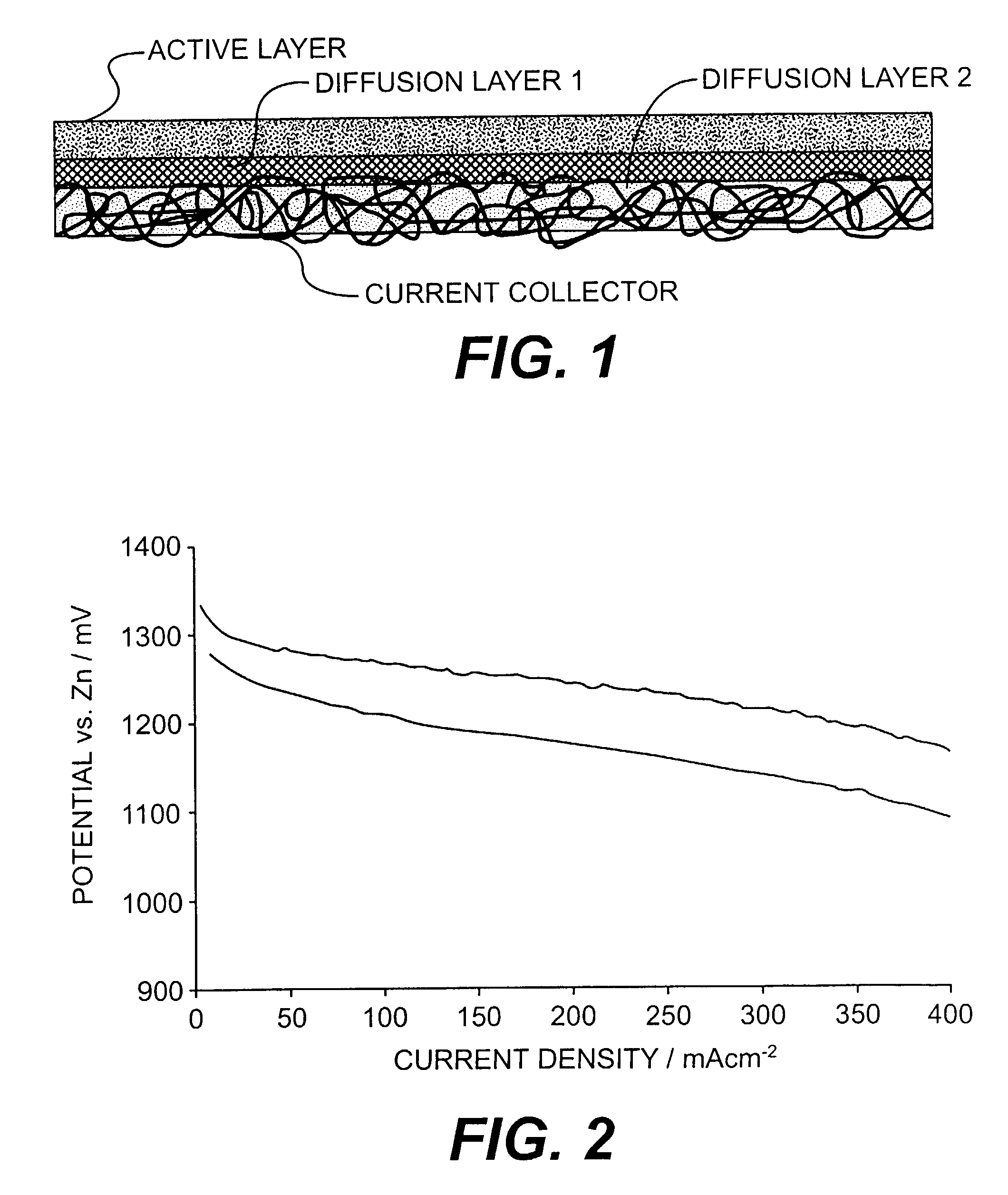
[0067]12.0 g of Shawinigan Black (from Chevron Chemicals, USA), 5.6 g polyethylene (S-379N from Shamrock, USA) and 2.0 g polytetrafluoroethylene (TF 9207 Hostaflon from Dyneon GmbH, Germany) were milled five minutes in an high speed mixer. Then, the mixture was suspended in 600 mL of toluene containing 0.4 g of solved polyisobutene (Oppanol®, from BASF, Germany) at ambient temperature for 30 minutes stirring magnetically. The suspension was filtered and the “dough” was kneaded three times through a small pasta machine. The wet dough was filled into a bottle which could be closed tight (L1 and L2).

[0068]17.0 g...

example 3

[0073]100 g of Cabot Vulcan XC-72 was treated the same way as described in example 1.

[0074]A 11 cm×11 cm piece of nickel foam (511 g / m2; 1.7 mm thick; from Retec, USA) was treated the same way as described in example 1.

[0075]14.0 g of Shawinigan Black (from Chevron Chemicals, USA) and 5.6 g polyethylene (S-379N from Shamrock, USA) were milled five minutes in an high speed mixer. Then, the mixture was suspended in 600 mL of toluene containing 0.4 g of solved polyisobutene (Oppanol®, from BASF, Germany) at ambient temperature for 30 minutes stirring magnetically. The suspension was filtered and the “dough” was kneaded three times through a small pasta machine. The wet dough was filled into a bottle which could be closed tight (L1 and L2).

[0076]17.6 g of activated Vulcan XC-72 and 1.0 g polyethylene (S-379N) were treated the same way as described above to form a second dough (L3).

[0077]The layers L1, L2 and L3 were formed exactly the same way as described in example 2.

[0078]After press...


PUM

PropertyMeasurementUnit
densityaaaaaaaaaa
densityaaaaaaaaaa
temperatureaaaaaaaaaa

Abstract

Fuel cell electrodes are described which comprise a non-woven network of conductive fibers, such as a carbon fleece, nickel foam sheet or stainless steel wool layer, plus additional activated carbon material, carrying one or more catalyst components and at least one polymeric substance as binder and / or repellancy agent to establish three zone interfaces (liquid-solid-liquid) or three phase interfaces (gas-liquid-solid). The electroactive catalyzed material is embedded into the conductive structure by specified deposition processes, such as coating, blading or spraying.

Description

[0001]This is a Continuation of International Application No. PCT / US01 / 41388, which was filed on Jul. 25, 2001, and claims the benefit of U.S. Provisional Application No. 60 / 220,655, which was filed on Jul. 25, 2000, the contents of both of which are incorporated by reference in their entirety.BACKGROUND OF THE INVENTION[0002]1. Field of the Invention[0003]The present invention relates to novel electrode structures which are of use in electrochemical devices, particularly fuel cells, and it teaches new processes for the manufacture of electrode and stack designs. The invention improves also alkaline direct methanol fuel cells.[0004]2. Description of Related Art[0005]Electrochemical cells invariably comprise at their fundamental level a solid or liquid electrolyte and two electrodes, the anode and cathode, at which the desired electrochemical reactions take place. Porous electrodes are employed in a range of electrochemical devices, in which a gaseous or liquid reactant and / or produc...

Claims


Application Information

Patent Timeline
Patent Type & Authority Patents(United States)
IPC IPC(8): H01M4/86A47B77/08H01M4/88H01M4/92H01M4/96H01M8/02H01M8/04H01M8/08H01M8/10
CPCH01M4/8605H01M4/8821H01M4/8835H01M4/8839H01M4/886H01M4/8896H01M4/926H01M4/96H01M8/0206H01M8/0221H01M8/0234H01M8/0239H01M8/0243H01M8/0245H01M8/04276H01M8/08H01M4/8807Y02E60/50H01M8/0215H01M8/0236H01M8/04097H01M8/1009Y02E60/523
Inventor KORDESCH, KARLCIFRAIN, MARTIN
Owner APOLLO ENERGY SYSTEMS
Why Eureka
Try Eureka