Multilayered golf ball and composition

Inactive Publication Date: 2006-03-21
ACUSHNET CO
View PDF176 Cites 6 Cited by
  • Summary
  • Abstract
  • Description
  • Claims
  • Application Information

AI Technical Summary

Benefits of technology

[0054]In one embodiment, the inner cover layer has a first hardness and the outer layer has a second hardness greater than the first hardness. When the cover hardness is greater than the inner cover layer and has a flexural modulus of greater than about 60,000 psi, the ball will exhibit low spin off of the driver for excellent distance. In another embodiment,

Problems solved by technology

However, none of the patents discussed above disclose the multilayer ball of the current invent

Method used


Image

  • Multilayered golf ball and composition
  • Multilayered golf ball and composition
  • Multilayered golf ball and composition

Examples


Example

Example 1

[0269]The cores of multilayer balls were formed by compression molding a blend of the batch formulation set forth in Table 1 below.

[0270]TABLE 1Core Batch FormulationMaterialParts Per HundredPolybutadiene (Cariflex 1220)76.0Rubber (Neocis BR-40)24.0Pigment0.03Zinc Diacrylate25.3Zinc Oxide2.1Regrind6.5Peroxide (Varox 231 XL)0.43Peroxide (Elastochem DBDB EF-60)0.16Density Adjusting Filler22.6

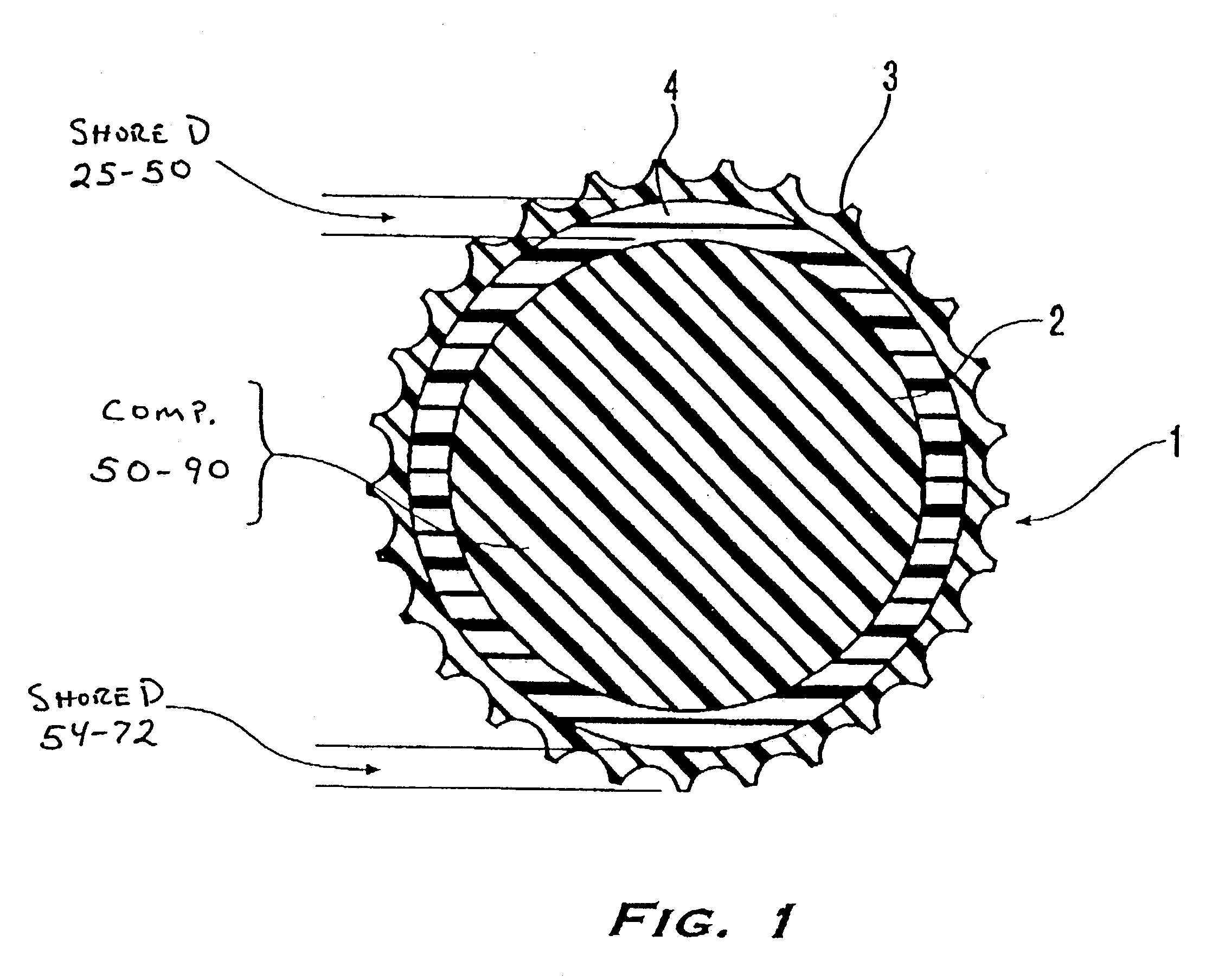
[0271]All of the cores had a diameter of about 1.39 inches and were measured to have compressions ranging from about 47 to 53 and specific gravities of about 1.138 to 1.156. For the above core batch formulation, the resultant cores were measured to have a compression of 50. The intermediate layer blends of Table 2 were subsequently injection molded about the cores of Table 1 at a temperature of about 375° F. to form the intermediate layers of the balls having an outer diameter of about 1.51 inches.

[0272]TABLE 2Intermediate Layer FormulationExample 1Example 2Formulation(weight percent)(wei...

Example

Example 2

Golf Ball Produced with a Diol Curing Agent

[0276]Two identically constructed golf balls were prepared, each with a liquid-filled center, a wound layer, and a cover. The first golf ball control formulation had a cover formed of a control formulation employing conventional polyurethane composition technology. In the second golf ball experimental formulation, the cover layer was formed with the thermoplastic polyurethane composition of the present invention, including a reaction product of 4,4′-diphenylmethane diisocyanate, polytetramethylene ether glycol, and mixtures of 1,3-bis-(2-hydroxyethoxy)benzene and 1,3-[bis-(2-hydroxyethoxy)]-diethoxy benzene. A color dispersion was added to both formulations. The golf ball products were processed according to methods described in the U.S. Pat. Nos. 5,733,428 and 5,888,437. The formulations of both golf balls are set forth in Table 4 below.

[0277]TABLE 4FormulationsMaterialsControlInventionMDI-PTMEG1eq.1eq.Prepolymer1HER-TG 2502—0.95e...

Example

Example 3

Golf Ball Prepared with a Secondary Diamine Curing Agent

[0280]Two identically constructed golf balls were prepared, each with a liquid-filled center, a wound layer, and a cover. The first golf ball control formulation had a cover formed of a control formulation employing conventional polyurethane composition technology. In the second golf ball experimental formulation, the cover layer was formed with the thermoplastic polyurethane composition of the present invention, including a reaction product of 4,4′-dicyclohexylmethane diisocyanate, polytetramethylene ether glycol and 4,4′-bis-(sec-butylamino)-dicyclohexylmethane. A color dispersion was added to both formulations. The golf ball products were processed according to methods described in the U.S. Pat. Nos. 5,733, 428 and 5,888,437. The formulations of both golf balls are set forth in Table 6 below.

[0281]TABLE 6FormulationsMaterialsControlInventionMDI-PTMEG Prepolymer11eq.H12MDI-PTMEG / polycaprolactone1eq.Prepolymer2CLEARLI...


PUM

PropertyMeasurementUnit
Thicknessaaaaaaaaaa
Thicknessaaaaaaaaaa
Thicknessaaaaaaaaaa

Abstract

A multilayer golf ball formed of a core, a cover layer and an optional intermediate layer disposed between the core and cover, wherein at least one layer includes a composition including a diisocyanate, a polyol or amine-terminated compound, and a curing agent, wherein the curing agent includes a diol or secondary diamine.

Description

CROSS-REFERENCE TO RELATED APPLICATIONS[0001]This application is a continuation-in-part of U.S. patent application Ser. No. 09 / 756,761, filed Jan. 10, 2001, now U.S. Pat. No. 6,645,091, which is a continuation-in-part of U.S. patent application Ser. No. 09 / 311,591, filed May 14, 1999, now U.S. Pat. No. 6,210,294, and also a continuation-in-part of U.S. patent application Ser. No. 10 / 051,121, filed Jan. 22, 2002, now U.S. Pat. No. 6,673,859, which is a continuation of U.S. patent application Ser. No. 09 / 404,146, filed Sep. 27, 1999, now U.S. Pat. No. 6,355,715, which is a continuation-in-part of U.S. patent application Ser. No. 08 / 996,718, filed Dec. 23, 1997, now U.S. Pat. No. 6,124,389, which is a continuation-in-part of U.S. patent application Ser. No. 08 / 603,057, filed Feb. 16, 1996, now U.S. Pat. No. 5,759,676, which is a continuation-in-part of U.S. patent application Ser. No. 08 / 482,522, filed Jun. 7, 1995, now U.S. Pat. No. 5,688,191. The entire disclosures of these applicati...

Claims


Application Information

Patent Timeline
IPC IPC(8): A63B37/12A63B37/00B29C43/30C08G18/10C08G18/48C08L9/00C08L23/08C08L75/08C09D175/04
CPCA63B37/0003C09D175/04C08L75/08C08L23/08C08L9/00C08G18/4854C08G18/10C08G18/3215A63B37/0024B29C2043/3644B29C43/305A63B37/0075A63B37/0031A63B37/0033A63B37/0037A63B37/0043A63B37/0045A63B37/0064C08L2666/14C08L2666/04C08L2666/24
Inventor RAJAGOPALAN, MURALIWU, SHENSHEN
Owner ACUSHNET CO
Why Eureka
Try Eureka