Exhaust-gas turbocharger for an internal combustion engine with variable turbine geometry

Inactive Publication Date: 2006-04-04
DAIMLER AG +1
View PDF9 Cites 27 Cited by
  • Summary
  • Abstract
  • Description
  • Claims
  • Application Information

AI Technical Summary

Benefits of technology

[0009]The rear face of this supporting wall is exposed to the exhaust gas in the inflow duct so that not only the front face of the support wall in the region of the variable turbine geometry but also the rear face of the support wall comes into contact with the exhaust gas and the surface of the support wall is heated substantially uniformly, which leads to a reduction in thermal stresses in this component. As a result, the thermal expansion of the support wall approximately corresponds to the expansion of the opposite, second support wall, so that the relative distance between the two support walls remains substantially unchanged over a wide range of temperatures, and undesirable air flows between the end faces of the radial guide vanes and the delimiting supporting walls are avoided.
[0010]A further advantage resides in the mechanical de-coupling of the support wall which projects into the exhaust gas inlet passage from the casing of the turbine. Unlike in the prior art, the projecting support wall is only connected to the casing of the turbine at one end thereof, with the result that the transmission of vibrations between casing and projecting support wall is reduced compared to designs in which there is contact with the casing over the entire surface of one side of the wall. Moreover, the projecting support wall has a greater degree of resilience, since the support wall projects freely into the inflow duct and is not supported over a large area to a component fixed to the casing.
[0011]The mechanical de-coupling effect can be increased by means o

Problems solved by technology

Undesirable incorrect air flows of this nature may be produced by gaps which may form in the region where the radial guide vanes are held in place at the end faces of the guide vane

Method used


Image

  • Exhaust-gas turbocharger for an internal combustion engine with variable turbine geometry
  • Exhaust-gas turbocharger for an internal combustion engine with variable turbine geometry
  • Exhaust-gas turbocharger for an internal combustion engine with variable turbine geometry

Examples


Example

[0021]Throughout the following figures, identical components are in each case provided with the same reference numerals.

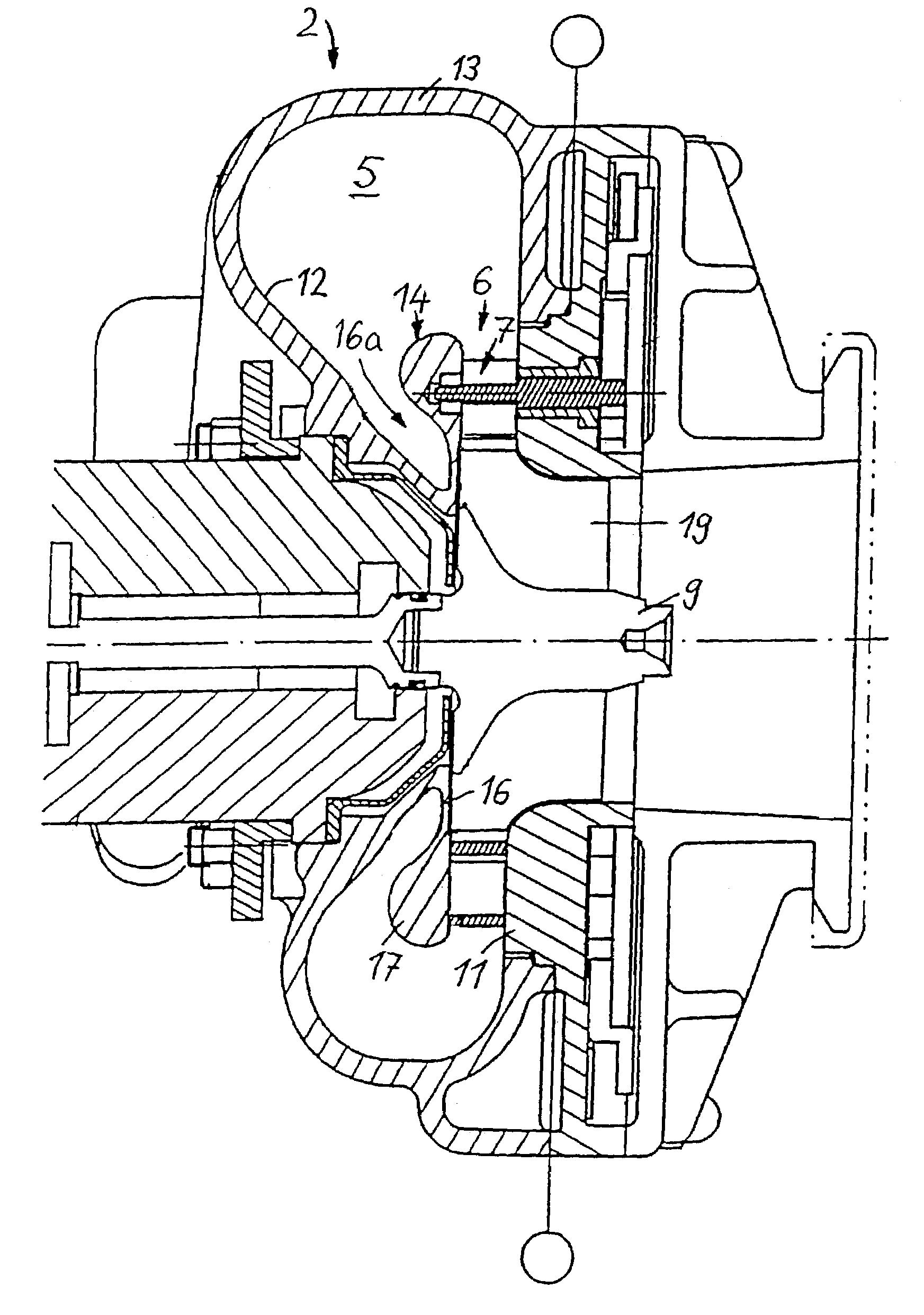
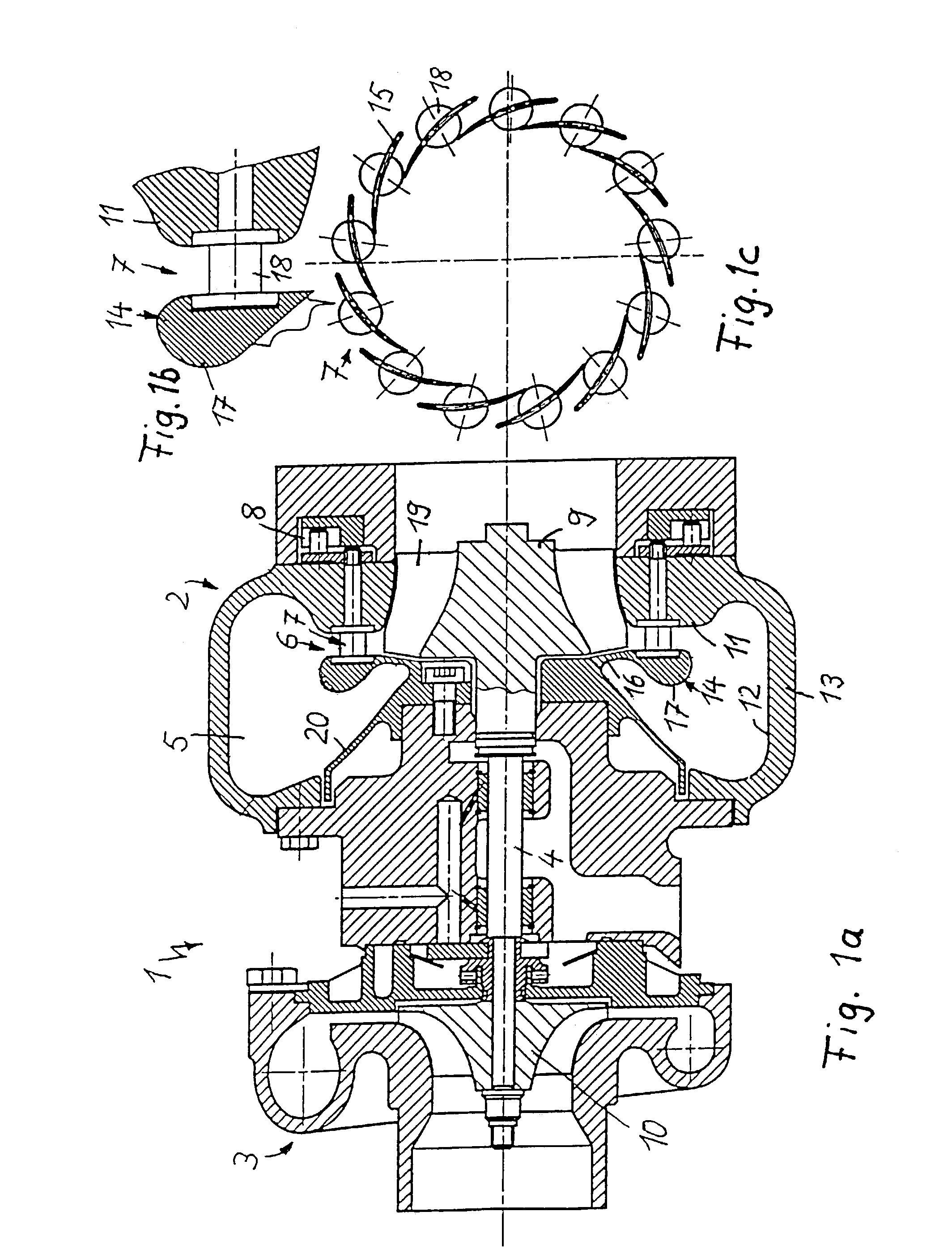
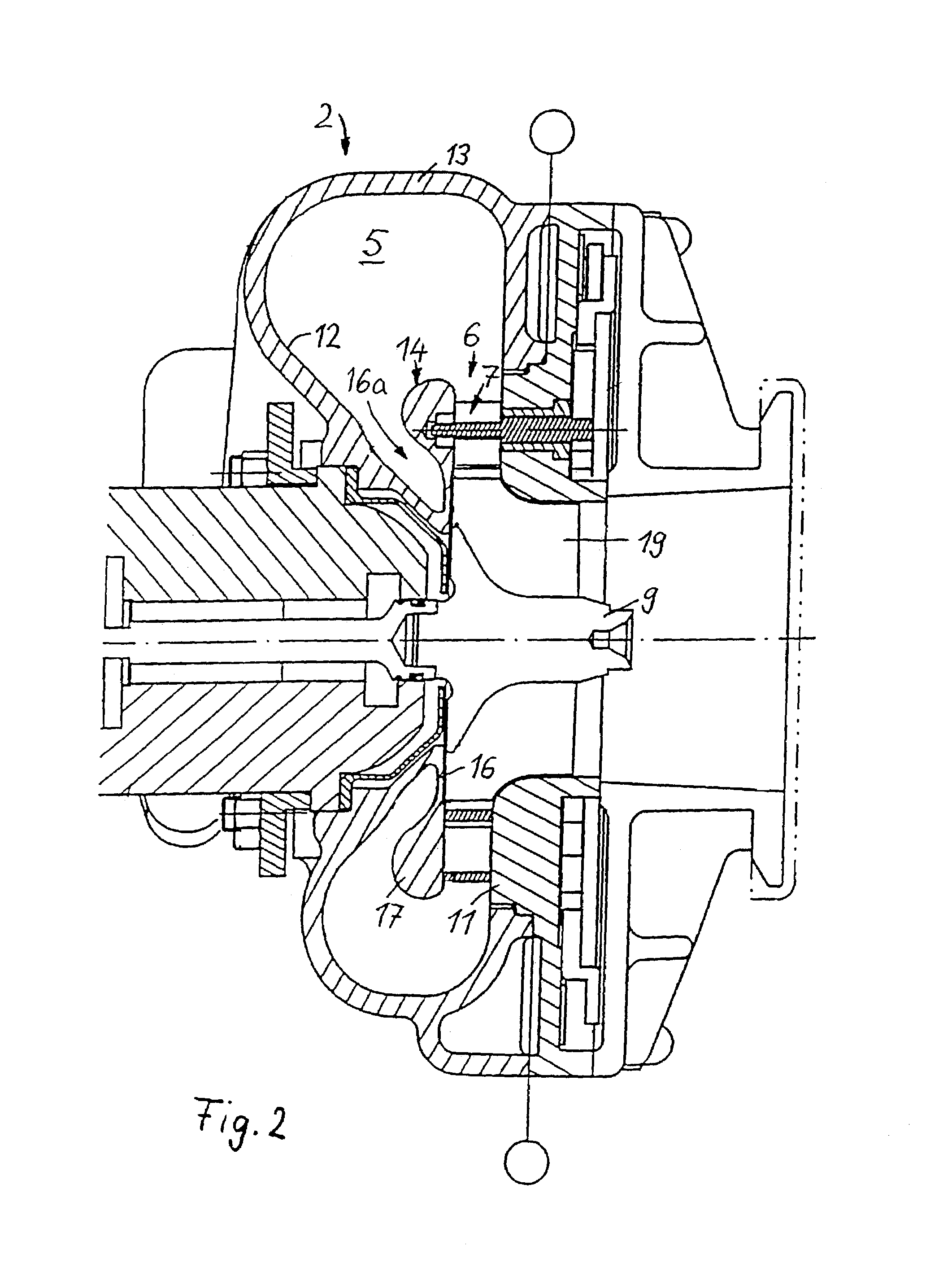
[0022]The exhaust-gas turbocharger 1 for an internal combustion engine, which is illustrated in FIG. 1a, comprises an exhaust-gas turbine, in the form of a radial turbine 2, and a compressor 3. A turbine wheel 9 of the radial turbine 2 is connected in a rotationally fixed manner, via a shaft 4, to a compressor impeller 10 of the compressor 3. When the internal combustion engine is operating, exhaust gas from the engine is passed into a radial gas inlet duct of the radial turbine and fed via a radial inlet flow passage to the turbine wheel 9, the rotation of which is transmitted via the shaft 4 to the compressor impeller 10. As a result, combustion air, which has been sucked into the compressor 3, is compressed and is fed to the cylinder intake passages of the engine.

[0023]A variable turbine vane structure 7, which can be adjusted, by means of an actuating device 8,...


PUM


Abstract

In an exhaust gas turbocharger for an internal combustion engine comprising a radial flow exhaust gas turbine and a compressor, which is connected to the turbine via a shaft, the turbine having a radial inflow duct and a radial inlet flow passage, which leads to the turbine wheel and in which a variable geometry vane structure for changing the cross-section of the radial inlet flow passage is supported between two support walls fixed to the turbine casing, one of the support walls projects into the inflow duct, in such a manner that the rear side of this support wall is spaced from the inner wall of the inflow duct wall so that the exhaust gas within the inflow duct is in contact also with the rear side of this support wall.

Description

[0001]This is a Continuation-In-Part application of international application PCT / EP01 / 10615 filed Sep. 14, 2001 and claiming the priority of German application 100 48 105.1 filed Sep. 28, 2000.BACKGROUND OF THE INVENTION[0002]The invention relates to a gas-exhaust gas turbocharger for an internal combustion engine with variable turbine geometry.[0003]DE 35 41 508 C1 discloses an exhaust-gas turbocharger, the exhaust-gas turbine of which is designed as a radial turbine which has a radial inflow passage through which exhaust gas flows via a radial flow inlet cross-section into the turbine section and onto a turbine wheel. A variable turbine geometry in the form of a guide vane ring with adjustable guide vanes, is arranged in the flow inlet cross-section. The guide vanes can be adjusted between a throttling position, which reduces the free flow inlet cross-section to the turbine wheel, and an open position, which widens the flow inlet cross-section as a function of the current operati...

Claims


Application Information

Patent Timeline
IPC IPC(8): F02D23/00F01D17/12F02B37/12F04B17/00F02B39/00F01D17/16F02B37/24F02C6/12
CPCF01D17/165F02C6/12F02B37/025Y02T10/144Y02T10/12
Inventor SUMSER, SIEGFRIEDFLEDERSBACHER, PETERHEMER, HANS-JOSEFKOCH, RALF
Owner DAIMLER AG
Why Eureka
Try Eureka