Driving circuit for a control terminal of a bipolar transistor in an emitter-switching configuration having a resonant load

a technology of bipolar transistors and control terminals, which is applied in the direction of transistors, electrical devices, pulse generators, etc., can solve the problems of high cost, simple and expensive driving circuit of fig. 1, and the fact that the choice of mos power transistors is particularly expensiv

Inactive Publication Date: 2006-04-04
STMICROELECTRONICS SRL
View PDF3 Cites 11 Cited by
  • Summary
  • Abstract
  • Description
  • Claims
  • Application Information

AI Technical Summary

Benefits of technology

[0024]Another aspect of the present invention is directed to a method for driving a control terminal of a bipolar transistor in an emitter-switching configuration between a resonant load and a voltage reference, with the bipolar transistor comprising a control terminal and a collector terminal. The method comprises applying a first voltage via at least one capacitor to the control terminal of the bipolar transistor, with the at least one capacitor being connected between the control terminal of the bipol

Problems solved by technology

This is the case for rice cooker devices, for example, whose waveforms are indicated by way of example in FIG. 2 for an operating frequency of 35 kHz and with a highest collector current of about 40 A. In this case, the driving circuit of FIG. 1 is straightforward but expensive.
This known approach is thus effective from a performance point of view, but is very expensive.
In fact, in view of voltage levels, current va

Method used


Image

  • Driving circuit for a control terminal of a bipolar transistor in an emitter-switching configuration having a resonant load
  • Driving circuit for a control terminal of a bipolar transistor in an emitter-switching configuration having a resonant load
  • Driving circuit for a control terminal of a bipolar transistor in an emitter-switching configuration having a resonant load

Examples


Embodiment Construction

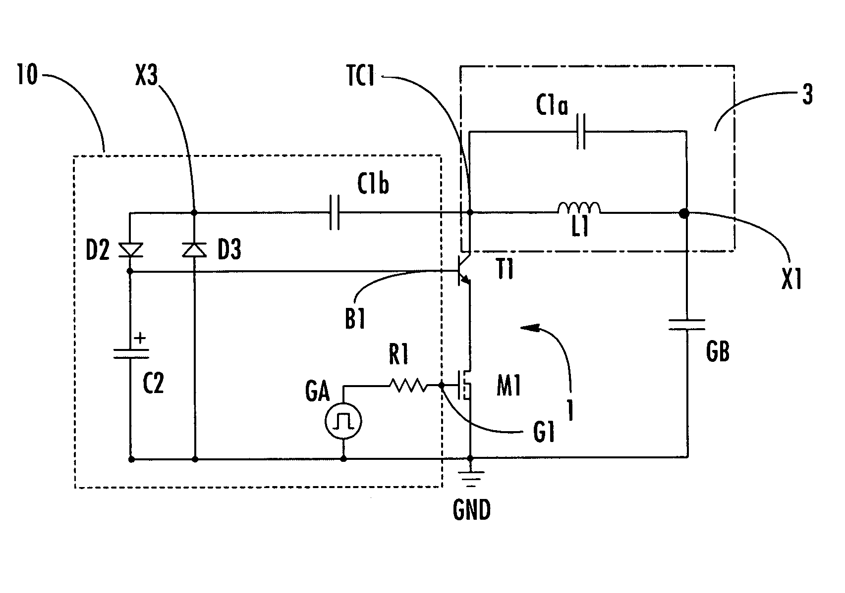
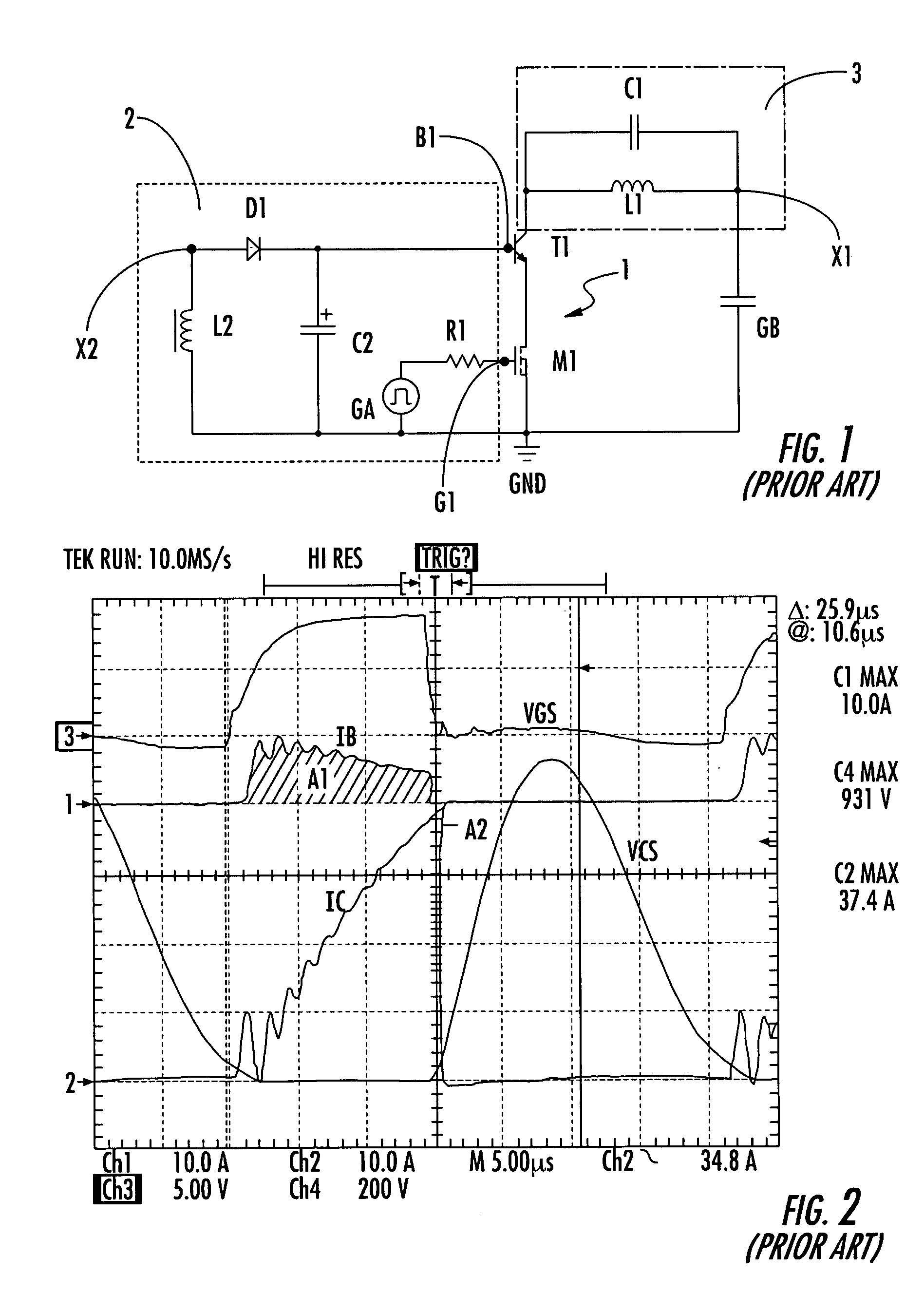
[0032]With reference to the figures, and particularly to FIG. 5, a driving circuit for an emitter-switching configuration with a resonant load according to the invention is schematically indicated with reference numeral 10. Elements that are structurally and functionally identical to those described with reference to FIG. 1 have been given the same reference numerals.

[0033]The driving circuit 10 is associated with an emitter-switching configuration 1 comprising a bipolar transistor T1 and a MOS transistor M1 cascode-connected to each other. The emitter-switching configuration 1 is connected between a load 3 and a voltage reference, such as ground GND.

[0034]As stated above, the emitter-switching configuration 1 provides that the bipolar transistor T1 is of the HV (High Voltage) type, i.e., a high breakdown voltage transistor, while the MOS transistor M1 is of the LV (Low Voltage) type, i.e., a low breakdown voltage transistor. The bipolar transistor T1 has a collector terminal connec...


PUM


Abstract

A driving circuit is provided for a control terminal of a bipolar transistor in an emitter-switching configuration. The emitter-switching configuration is between a resonant load and a voltage reference. The driving circuit includes at least one capacitor between the control terminal of the bipolar transistor and the voltage reference. The driving circuit further includes an additional resonance capacitor between a collector terminal of the bipolar transistor and a circuit node, a first diode between the circuit node and the control terminal, and a second diode between the circuit node and the voltage reference.

Description

FIELD OF THE INVENTION[0001]The present invention relates to a driving circuit for a control terminal of a bipolar transistor in an emitter-switching configuration with a resonant load, and to a corresponding method for driving the same.BACKGROUND OF THE INVENTION[0002]An emitter-switching circuit configuration comprises a bipolar transistor having a high breakdown voltage connected to a low voltage power MOSFET transistor. Such a configuration is schematically shown in FIG. 1 and is indicated with reference numeral 1. The emitter-switching configuration 1 comprises a bipolar transistor T1 and a MOS transistor M1 cascode-connected together between a load 3 and a voltage reference, such as ground GND.[0003]The emitter-switching configuration 1 provides that the bipolar transistor T1 is of the high voltage (HV) type, i.e., a high breakdown voltage transistor, while the MOS transistor M1 is of the low voltage (LV) type, i.e., a low breakdown voltage transistor. The bipolar transistor T...

Claims


Application Information

Patent Timeline
IPC IPC(8): H03K3/00H03K17/042H03K17/567
CPCH03K17/567H03K17/04213
Inventor SCOLLO, ROSARIOBUONOMO, SIMONE
Owner STMICROELECTRONICS SRL
Why Eureka
Try Eureka