High-speed, belt-driven industrial blower

a belt-driven, industrial blower technology, applied in the direction of positive displacement liquid engine, piston pump, liquid fuel engine, etc., can solve the problems of reducing overall life, limiting not only the delivery pressure (i.e., gas or air temperature rise), but also the ability to manage the thermal dissipation in the critical area, etc., to achieve the effect of improving life expectancy

Active Publication Date: 2006-04-18
VORTECH ENG
View PDF5 Cites 13 Cited by
  • Summary
  • Abstract
  • Description
  • Claims
  • Application Information

AI Technical Summary

Benefits of technology

[0020]The present invention resides in a high-speed, belt-driven centrifugal blower having design characteristics which markedly improve life expectancy.
[0021]In one embodiment, the blower incorporates a self-contained air cooling system. The blower generally comprises a housing having air inlet and outlet apertures. Typically, the housing is comprised of a mounting plate and a cover attached to the mounting plate. Inlet apertures are typically formed in the cover, and the outlet apertures are formed in the mounting plate. To reduce noise, the cover preferably includes a sound dampening material.
[0025]A belt interconnects the drive pulley and a pulley of the spindle assembly, which powers the centrifugal compressor. A belt tensioning assembly is typically connected to the belt, and includes an automatic belt tensioner coupled to an idler. As described above, as the drive pulley is rotated by the drive motor, the belt causes a shaft of the spindle assembly to rotate and power the centrifugal compressor. Rotation of the drive pulley also causes air to enter the housing through the inlet apertures, flow over the belt and spindle assembly, and exit through the outlet apertures, thus cooling the entire drive assembly and prolonging the life of the blower.
[0026]In another embodiment, the blower incorporates a spindle assembly having a rigid bearing arrangement. The spindle assembly generally comprises a housing having a pulley end portion and an impeller end portion. A rotatable shaft extends through the housing to interconnect the pulley and the impeller. A bearing element is disposed between the shaft and the housing at the pulley end portion, and a bearing element is disposed between the shaft and the housing at the impeller end portion. The bearing elements comprise ball bearings disposed between inner and outer races, having offset grooves formed therein. Typically, the bearing elements are angular contact-type. Preferably, multiple bearing elements are disposed at either or both ends. The use of multiple bearing elements allows load sharing and enables reduction of load on any individual bearing, and hence a reduced fraction of dynamic load rating capacity. This results in markedly improved life expectancy.
[0029]To cool the spindle assembly, air vents are formed in the housing thereof. Also, the spindle assembly housing includes an inner sleeve comprised of a metal having a first coefficient of thermal expansion similar to the other internal components, and an outer casing attached to the inner sleeve and comprised of a metal having a second coefficient of thermal expansion. This enables heat dissipation while maintaining the rigid pre-loading arrangement described above.

Problems solved by technology

Current blower products are all very similar in design and performance, and all suffer from the same performance limitations.
Understanding that air compression necessarily raises the process gas (air) temperature, the spindle housing and thus the critical high-speed bearing elements are exposed directly to the hotter compressed-air stream, limiting not only delivery pressures (i.e., gas or air temperature rise) but also the ability to manage thermal dissipation in the critical precision bearing elements.
Increased bearing operating temperature has been shown to reduce overall life, shorten lubricant life and pose limitations on speed.
This scheme, unfortunately, reduces specific speed of the compressor machinery aspect with the adjunct result of reducing compressor efficiency.
Reduced compressor efficiency, on the other hand, leads directly to increased drive power requirements (hence more load and heat generated within bearings, belt and idler) and increased discharge gas-air temperatures, resulting in even less cooling efficacy.
Belt manufacturers, in fact, state that an 18° F. operating temperature rise within the belt may reduce life by a factor of one-half.
Even so, any applied axial load which is sufficient to compress the spring 8 beyond its pre-loaded working height will effectively “unload” the bearing element 5 or 6 on the opposite end, leading to instability and potential failure.
Predicting and controlling thrust loads, due to aerodynamic characteristics of the impeller 4, is very difficult and highly dependent on the operating point of the compressor.
Attempts to compensate for the un-loading of the opposite bearing, instability and rapid failures described above, by increasing spring pre-load of the spindle assemblies of prior art results in reduced operating life due to additional pre-load.
Positioning the spring at the pulley end, which is typical, is potentially troublesome as the heavy belt load, considering applied radial loads, attempts to misalign the bearing races of the bearing elements 5 and 6 at the adjacent bearing, and hence “skew” the ball track.
Increasing spring pre-load necessarily compromises bearing life, due in part to elevated spring load.
Attempting to add bearings, i.e., “duplex” them in order to improve load carrying characteristics of the individual bearings cannot be effectively accomplished with a spring-loaded system.
This is due to the poor stiffness characteristics of the spring system.

Method used


Image

  • High-speed, belt-driven industrial blower
  • High-speed, belt-driven industrial blower
  • High-speed, belt-driven industrial blower

Examples


Embodiment Construction

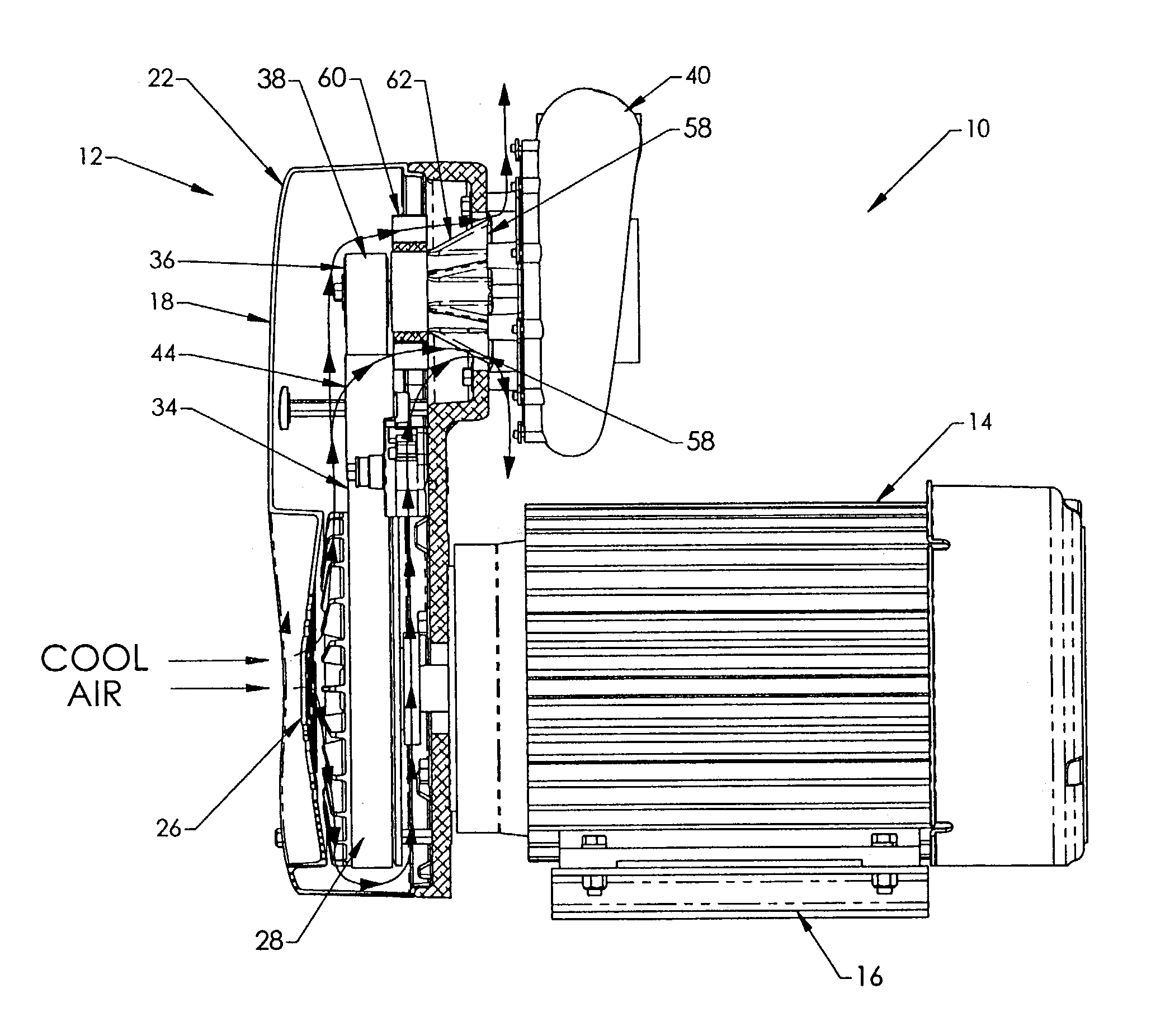
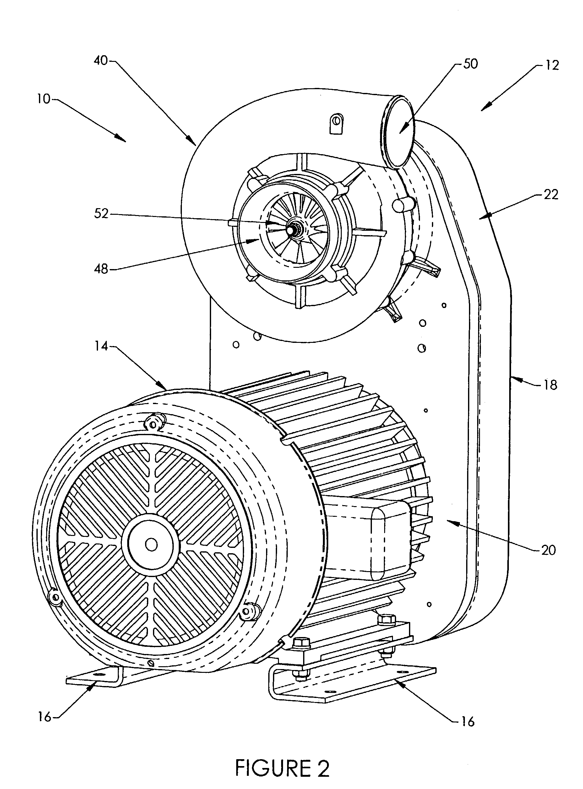
[0048]The present invention resides in a belt-driven industrial blower, generally referred to by the reference number 10 incorporating a self-contained air cooling system 12 for cooling various components of the blower 10 to prolong the longevity and useful life of the blower 10.

[0049]With reference now to FIGS. 2–5, the blower 10 includes an electric drive motor 14 having mounting supports 16 for attachment to the intended mounting surface, typically a floor. The mounting support 16 may include springs or dampeners for isolating the blower 10 from its surrounding to the greatest extent possible. A housing 18 has a back plate or mounting plate 20 thereof attached to the electric drive motor 14. A cover 22 of the housing 18 is removably attached to the mounting plate 20 by appropriate fasteners 24, such as nuts threaded onto bolts extending from the mounting plate 20. The cover 22 is preferably manufactured from robust, but sound absorbing / attenuating materials, for example, rota-mol...


PUM


Abstract

A centrifugal blower is provided which incorporates a self-contained air cooling system. The blower includes a drive assembly connected to a drive motor and disposed within a housing having inlet and outlet apertures. A centrifugal compressor is connected to the drive assembly and disposed exteriorly to the housing adjacent to the outlet apertures. Rotation of a drive pulley, including a fan, by the drive motor causes air to enter the housing through the inlet apertures, flow over components of the drive assembly, and exit through the outlet apertures. A spindle assembly having a rigid bearing arrangement is also provided. One or more bearing elements are disposed at opposite ends of a spacer and between a shaft and housing of the spindle assembly. Such rigid pre-loaded bearing arrangement eliminates “unloading” concerns, and allows load sharing between bearing elements.

Description

RELATED APPLICATION[0001]This application claims priority from U.S. Provisional Application Ser. No. 60 / 369,736, filed Apr. 4, 2002.BACKGROUND OF THE INVENTION[0002]The present invention generally relates to industrial blowers. More particularly, the present invention relates to a high-speed, belt-driven blower having an improved spindle assembly and an air cooling system in order to cool various components of the blower and improve the reliability and durability of the blower.[0003]Compact belt-driven centrifugal blowers are commonly used in air drying and blow-off applications. These types of applications include aqueous-based in-line process cleaners which are used in a variety of manufacturing industries, consisting of wash and blow-off / dry cycles all in one self-contained machine. Other applications include ultra-high performance air knives, high volume blow-off, and de-watering applications typical with canning, beverage and electronic industries. Such blowers are also used in...

Claims


Application Information

Patent Timeline
Patent Type & Authority Patents(United States)
IPC IPC(8): F04B17/00F04D25/02F04D29/04F04D29/056F04D29/059
CPCF04D25/02F04D29/059F04D29/0563
Inventor ANDERSON, ROBERT B.
Owner VORTECH ENG
Why Eureka
Try Eureka