
Desulfurizer comprising activated carbon and method of desulfurization

Inactive Publication Date: 2006-04-18
OSAKA GAS CO LTD +1
View PDF16 Cites 27 Cited by
  • Summary
  • Abstract
  • Description
  • Claims
  • Application Information

AI Technical Summary

Benefits of technology

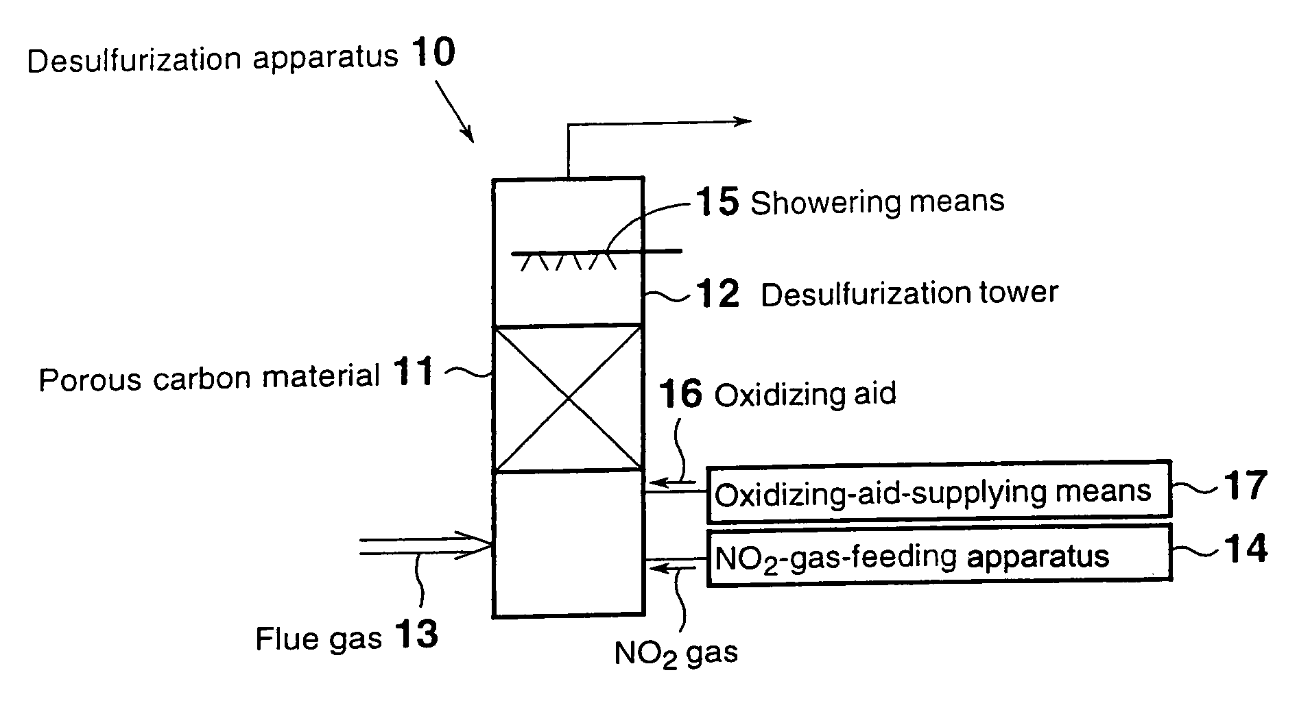
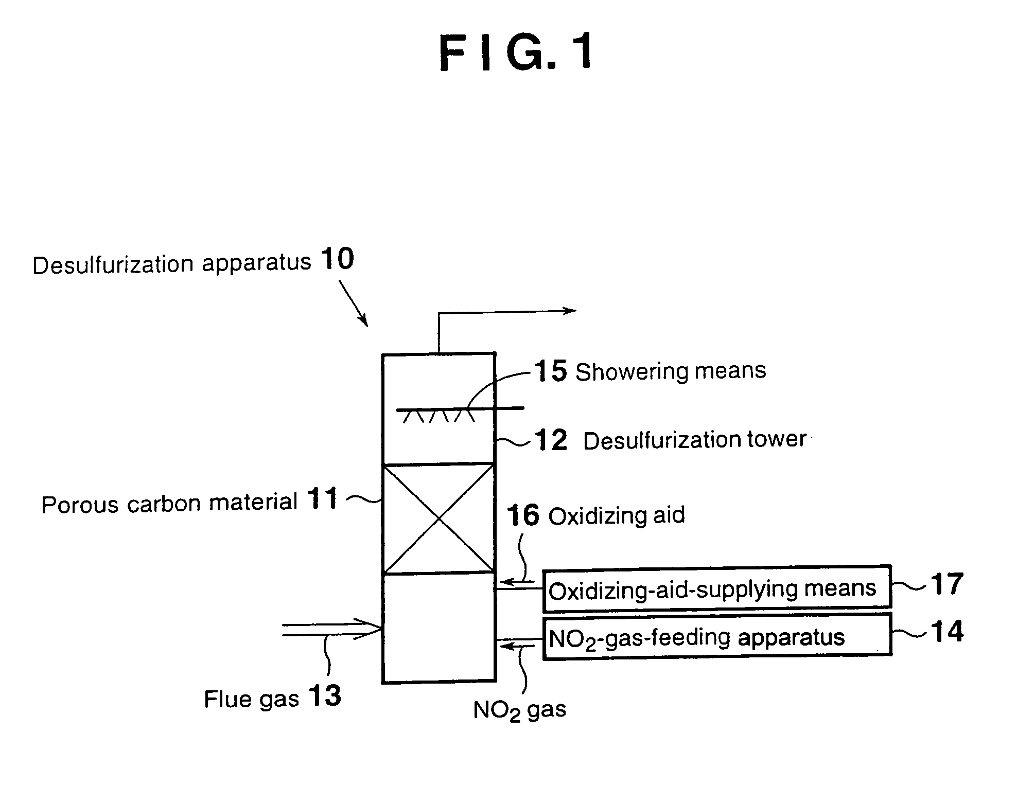
[0009]According to the first invention, an NO2-gas-feeding apparatus for feeding NO2 gas into the desulfurization tower is provided. Therefore, an effect of NO inhibiting performance of the porous carbon material is suppressed, thereby effectively desulfurizing a flue gas containing sulfur oxides.
[0037]According to the fifteenth invention, which is drawn to a specific embodiment of the desulfurization method of the tenth or eleventh invention, there is provided water-supply means for adjusting the water content of the flue gas in the desulfurization tower to that corresponding to saturation of water vapor or higher. Therefore, desulfurization can be performed effectively.

Problems solved by technology

However, the desulfurization has a drawback in that, when nitrogen monoxide (NO) is contained in the flue gas, catalytic effect of the porous carbon material is deteriorated, thereby deteriorating desulfurization performance.
In other words, the desulfurization has a drawback in that an excess amount of porous carbon material must be used in order to maintain desulfurization performance, resulting in an increase in treatment costs.

Method used


Image

  • Desulfurizer comprising activated carbon and method of desulfurization
  • Desulfurizer comprising activated carbon and method of desulfurization
  • Desulfurizer comprising activated carbon and method of desulfurization

Examples


first embodiment

[First Embodiment]

[0043]FIG. 1 is a schematic view of a flue gas desulfurization apparatus according to a first embodiment. As shown in FIG. 1, a desulfurization apparatus 10 of the first embodiment for desulfurizing a flue gas 13 containing sulfur oxides through contact with a porous carbon material 11 provided in a desulfurization tower 12, the porous carbon material 11 being at least one species selected from activated carbon and activated carbon fiber, contains an NO2-gas-feeding apparatus 14 for feeding NO2 gas into the desulfurization tower 12. Within the desulfurization tower 12, showering means 15 is provided at the top, the showering means adjusting the water content of the flue gas in the desulfurization tower to that corresponding to saturation with water vapor or higher at the treatment temperature.

[0044]The aforementioned porous carbon material 11 adsorbs sulfur oxides contained in the flue gas and serves as an oxidation catalyst.

[0045]No particular limitation is impose...

second embodiment

[Second Embodiment]

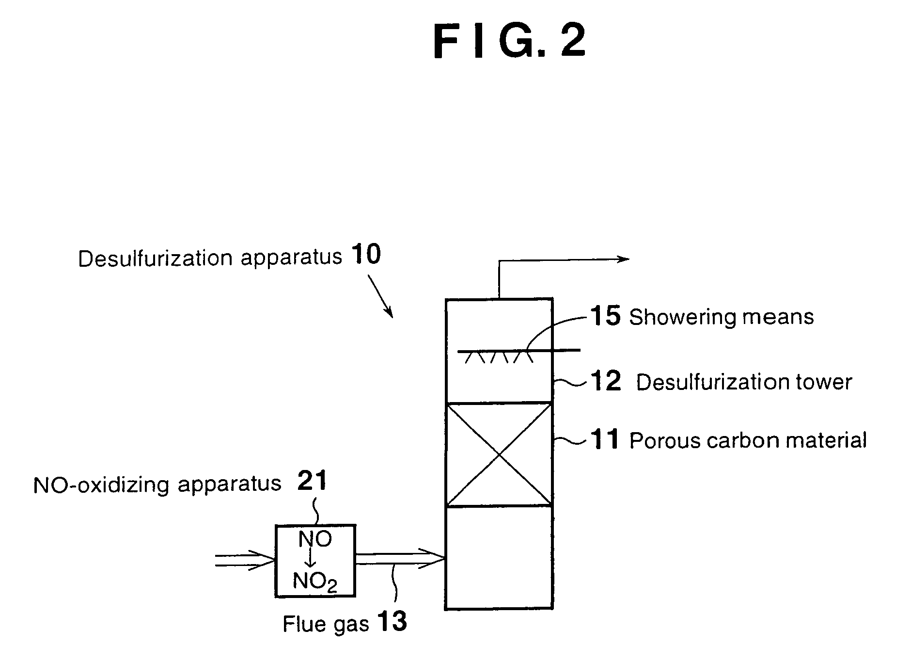
[0068]FIG. 2 is a schematic view of a flue gas desulfurization apparatus according to a second embodiment. Those elements that are also employed in the first embodiment are denoted by the same reference numerals, and descriptions thereof are omitted.

[0069]As shown in FIG. 2, a desulfurization apparatus 10 of the second embodiment for desulfurizing a flue gas 13 containing sulfur oxides through contact with a porous carbon material 11 provided in a desulfurization tower 12, the porous carbon material 11 being at least one species selected from activated carbon and activated carbon fiber, contains an NO-oxidizing apparatus 21 for oxidizing NO contained in the flue gas 13 to be fed into the desulfurization tower 12 to form NO2, the NO-oxidizing apparatus 21 being provided on the upstream side of the desulfurization tower 12.

[0070]In contrast to the first embodiment, in the second embodiment, NO contained in the flue gas 13 which has not yet been fed to the desulfuriz...

third embodiment

[Third Embodiment]

[0073]FIG. 3 is a diagram showing a flue gas treatment system provided with a flue gas desulfurization apparatus according to a third embodiment. As shown in FIG. 3, the system 30 of the third embodiment comprises NO-oxidizing apparatus 21 for oxidizing NO contained in a flue gas 13 discharged on a flue gas discharge line 32 from a boiler, a thermal power station, any of a variety of plants, or similar facilities 31, to form NO2; the aforementioned desulfurization apparatus 10; and an NOx-removing apparatus 33.

[0074]In this system, NO contained in the flue gas is oxidized in advance by means of the NO-oxidizing apparatus 21, thereby transforming into NO2. Thus, an effect of NO inhibiting performance of the porous carbon material during desulfurization carried out in the desulfurization apparatus 10 is suppressed, thereby increasing desulfurization efficiency.

[0075]Through desulfurization, the temperature of the flue gas 13 is lowered. Thus, an NOx-removing apparatu...


PUM

PropertyMeasurementUnit
Temperatureaaaaaaaaaa
Fractionaaaaaaaaaa
Fractionaaaaaaaaaa

Abstract

A desulfurization apparatus for desulfurizing a flue gas containing sulfur oxides through contact with a porous carbon material. The carbon material, which is provided in a desulfurization tower, is at least one species selected from activated carbon and activated carbon fiber. The apparatus contains an NO2-gas-feeding apparatus for feeding NO2 gas into the desulfurization tower. Within the desulfurization tower, a showering mechanism is provided at the top, the showering mechanism adjusting water content of the flue gas in the desulfurization tower to that corresponding to saturation with water vapor or higher at the treatment temperature.

Description

TECHNICAL FIELD[0001]The present invention relates to a desulfurization apparatus for removing sulfur oxides contained in a flue gas generated by a boiler or a similar facility employing a fuel such as coal, and to a method for desulfurizing the flue gas.BACKGROUND ART[0002]Flue gases generated by boilers and thermal power stations employing a fuel such as coal or heavy oil, or by plants such as chemical-production plants, metal-processing plants, sintering plants, and paper-making plants contain a large amount of sulfur oxides such as sulfur dioxide. Among flue gas desulfurization methods for removing the sulfur oxides, there is disclosed a method in which a flue gas is brought into contact with a porous carbon material such as activated carbon or activated carbon fiber, to thereby cause the porous carbon material to adsorb sulfur oxides such as sulfur dioxide contained in the flue gas; the sulfur oxides are oxidized with oxygen contained in the flue gas in the presence of the poro...

Claims


Application Information

Patent Timeline
IPC IPC(8): B01D53/50B01D53/56B01D53/86C01B17/78C01B17/80B01D53/60
CPCB01D53/60B01D53/50
Inventor YASUTAKE, AKINORIKOBAYASHI, NORIHISAKURISAKI, TAKASHIYOSHIKAWA, MASAAKI
Owner OSAKA GAS CO LTD
Learn More