
Method of fixing anodic arc attachments of a multiple arc plasma gun and nozzle device for same

Active Publication Date: 2006-04-18
SULZER METCO (US) INC
View PDF5 Cites 42 Cited by
  • Summary
  • Abstract
  • Description
  • Claims
  • Application Information

AI Technical Summary

Benefits of technology

[0013]The arc attachment point can move along the ridge as operating conditions change. This allows the arc length to vary in accordance with the changing operating conditions while still remaining at a radially fixed position. In addition, by allowing limited wandering, the erosive effects of the arc on the anode is spread, thereby increasing the lifetime of the anode.
[0014]Most preferably, the ridge is angled relative to the central axis. Angling the ridge increases the relative length of the arc attachment area. By increasing the area, the amount of thermal energy that can be transferred by the cooling system is also increased, allowing the gun to run hotter and / or last longer.
[0018]Advantageously, because the radial position of the arc attachment points remains substantially fixed, even as the gas mass flow and the amperage of the current flow change, the position of the plasma plumes also remains fixed. As a result, powder can be injected under substantially ideal conditions. This eliminates the need to periodically adjust the radial position of the powder injectors as operating conditions change to obtain an optimal injection position.
[0019]In accordance with a further aspect of the invention, a plasma generator can be provided that has a plurality of powder injection ports arranged in a substantially fixed configuration with relation to the arc attachment regions. In a particularly advantageous embodiment, the powder injection ports and the anode element can be formed as an integral member. This ensures proper alignment of the injection ports relative to the position of the plasma plumes and also reduces the number of parts in the gun, thereby improving reliability and reducing cost.

Problems solved by technology

As variations are introduced into the temperature and velocity of the powder, defects in the coating can result, reducing the overall effectiveness of the coating.
One drawback with this solution is that the positioning not always accurate.
In addition to human error and mechanical imprecision, there are also random fluctuations in power and / or input gas flow that will cause wandering of the arc attachment points and subsequent misalignment of the injectors.
Because the misalignment affects the temperature and velocity of the applied powder, the changes can result in inconsistent coatings being applied as the position of the injection relative to the plasma plumes varies.
Since the powder is typically the most expensive component of the coating process, even small changes in deposit efficiency can have non-trivial economic impact.

Method used


Image

  • Method of fixing anodic arc attachments of a multiple arc plasma gun and nozzle device for same
  • Method of fixing anodic arc attachments of a multiple arc plasma gun and nozzle device for same
  • Method of fixing anodic arc attachments of a multiple arc plasma gun and nozzle device for same

Examples


first embodiment

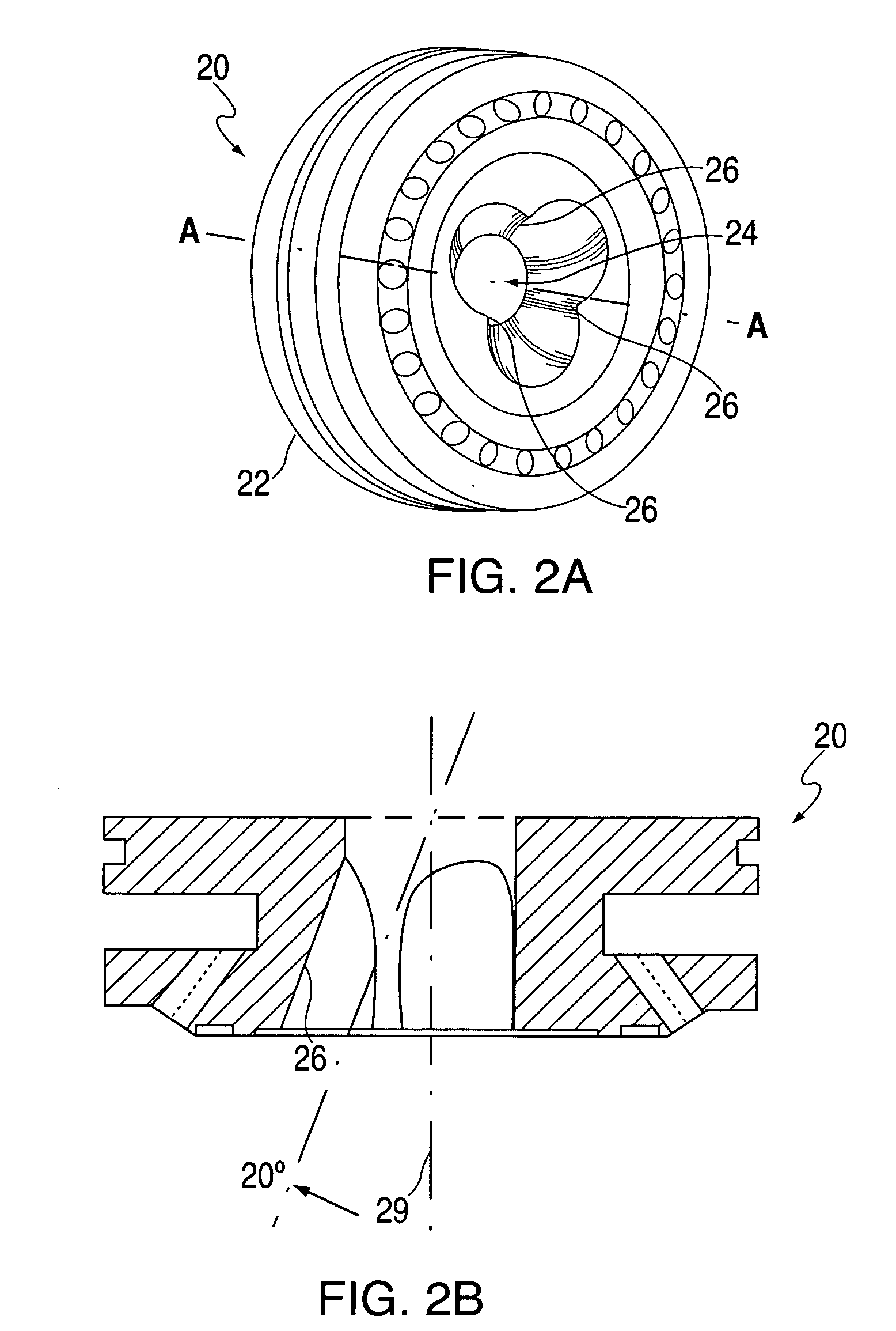
[0028]FIG. 2A shows a perspective view of an anode with radially fixed arc attachment points according to the invention 20. FIG. 2B shows a cut-away view of the anode in FIG. 2A along line A—A. With reference to FIGS. 2A and 2B, an anode element 22 has a central bore 24 in which are formed a plurality of arc attachment regions 26. Preferably, there are an odd number of arc attachment regions, which (with corresponding cathode elements in a plasma gun), will result in an equal number of plasma plumes. Odd numbers of plumes allow powder to be easily injected between two plumes and directly towards a third. Most preferably, three arc attachment regions are formed.

[0029]As illustrated, the anode element 20 is preferably a unitary element and the arc attachment regions are preferably formed by removing overlapping generally circular cylindrical areas, preferably having equal diameter and spaced symmetrically around the central axis 29 of the central bore. The remaining surface surroundin...

second embodiment

[0033]FIG. 3A shows a perspective view of an anode with radially fixed arc attachment points according to the invention 20′. FIG. 3B shows a front schematic view of the anode of FIG. 3A, while FIG. 3C is a cut-away view of the anode of FIG. 3B along line B—B.

[0034]With reference to FIGS. 3A–3C, the anode 22 is configured similar to that in FIGS. 2A–2B, having a central bore 24 along axis 29 and a series of cooling tubes 27. In this embodiment, however, the arc attachment regions are formed by inserting a series of pins 32 into corresponding openings 34 along the periphery of the inner bore. As illustrated, the openings are configured so that a portion of the inserted pins are exposed to the inner bore and are proud relative to adjacent areas of the surface of the central bore. The exposed proud surface of each pin forms an arc attachment region 36. In a preferred configuration, the anode element is substantially comprised of copper and the pins are comprised of tungsten. The positio...

third embodiment

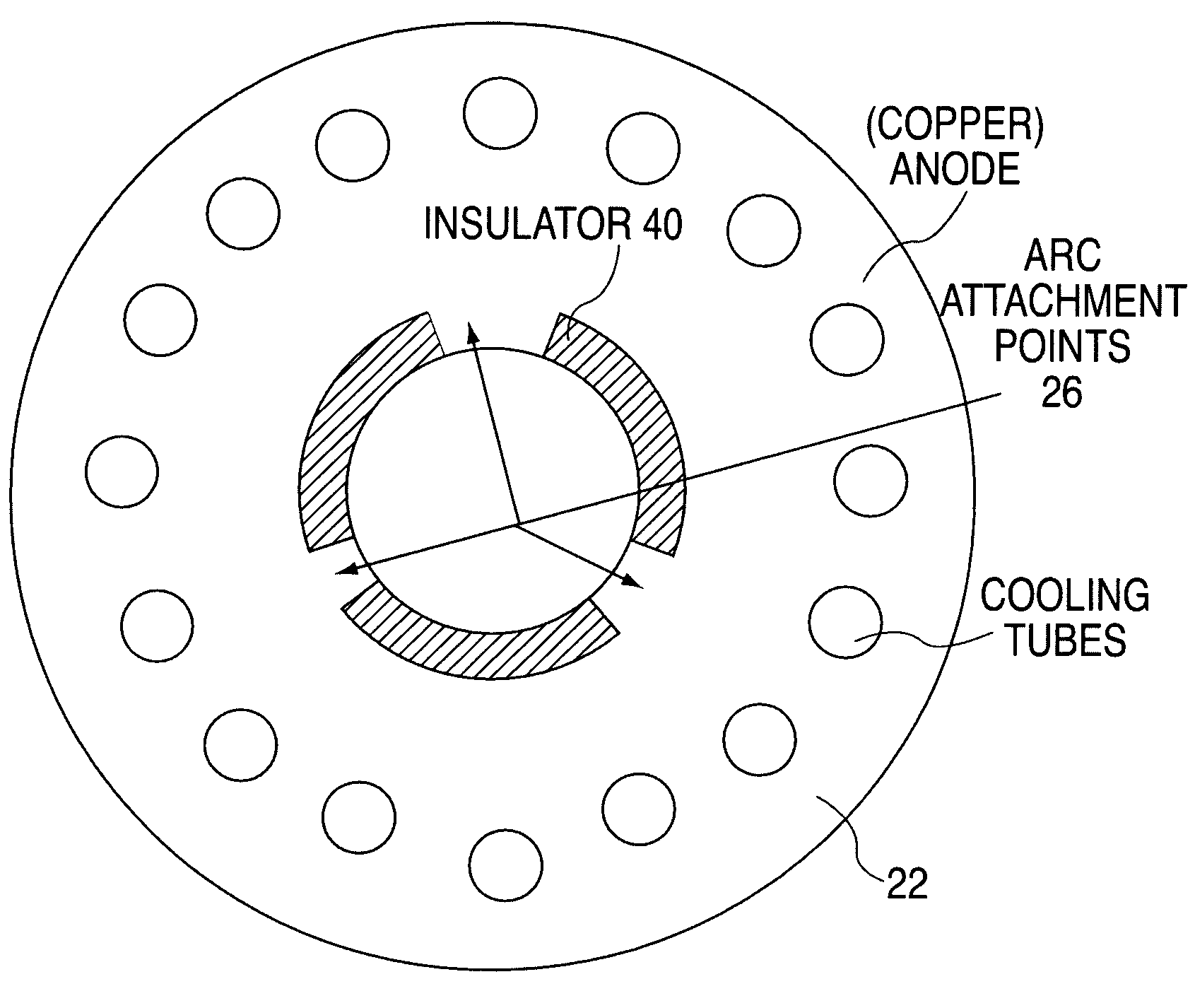
[0035]the invention is shown in FIG. 4. In this embodiment, regions of the central bore are lined with an electrical insulator 40. The desired arc attachment areas are left exposed. The arcs will attach to areas having lower resistivity and therefore will attach to the exposed areas as opposed to the areas which are insulated.


PUM

PropertyMeasurementUnit
Electrical conductivityaaaaaaaaaa
Diameteraaaaaaaaaa
Areaaaaaaaaaaa

Abstract

An improved anode element for a plasma generator is comprised of an anode body having a central bore therein. A plurality of arc attachment regions are formed along a surface of the central bore. Each attachment is configured to provide a substantially radially predefined attachment point for an electrical arc extending between the attachment region and a respective cathode when the anode element is used in a plasma generator. The arc attachment points can be areas along the central bore which are elevated or proud relative to adjacent areas. The attachment points can also be defined at least in part by asymmetrical cooling of the anode.

Description

FIELD OF THE INVENTION[0001]The present invention is directed to an improved multiple arc plasma torch and nozzle assembly.BACKGROUND[0002]A plasma gun or torch is a device used to apply spray coatings at high temperatures and velocities to a surface. A conventional plasma gun is comprised of generally tubular channel with a cathode assembly at one end and an anode assembly at the other. When a sufficiently high voltage is applied across the anode and cathode, an electric arc is generated. Gas is fed into the chamber at one end and is heated by the arc to form a plasma. An exit nozzle is provided at the other end of the chamber to direct the plasma. The powder to be sprayed is injected into the plasma stream. The powder is heated and accelerated by the plasma and can be sprayed onto a surface to be coated. By controlling the voltage and the rate of gas flow, the amount of heating and velocity of the generated plasma, and thus the temperature and spray velocity of the powder, can be ...

Claims


Application Information

Patent Timeline
IPC IPC(8): B23K10/00
CPCH05H1/34H05H2001/3452H05H1/3452
Inventor HAWLEY, DAVID
Owner SULZER METCO (US) INC
Learn More