Guidewire with multiple radiopaque marker sections

a technology of radiopaque marker and guidewire, which is applied in the field of catheters, can solve the problems of difficult to keep the patient sill, general time-consuming and relatively inaccurate methods of positioning the balloon member,

Inactive Publication Date: 2006-04-25
BOSTON SCI SCIMED INC
View PDF56 Cites 121 Cited by
  • Summary
  • Abstract
  • Description
  • Claims
  • Application Information

AI Technical Summary

Benefits of technology

[0014]The inventive method of positioning a balloon catheter relative to an artery stenosis begins by advancing the guide wire through the artery and across the stenosis such that a radiopaque marker on the guide wire pinpoints the location of the stenosis. The balloon catheter is subsequently advanced to the pinpointed location by aligning a radiopaque marker of the balloon member with the radiopaque marker on the guide wire corresponding to the location of the stenosis. Because this location is pinpointed relative to the radiopaque marker on the guide wire, additional dye is not needed to assure correc...

Problems solved by technology

However, because dye injections cause surgical complications, physicians derived disfavor injecting additional dye into the artery in order to properly position the balloon member.
As can be readily appreciated, these methods of positioning a balloon member a...

Method used


Image

  • Guidewire with multiple radiopaque marker sections
  • Guidewire with multiple radiopaque marker sections

Examples


Embodiment Construction

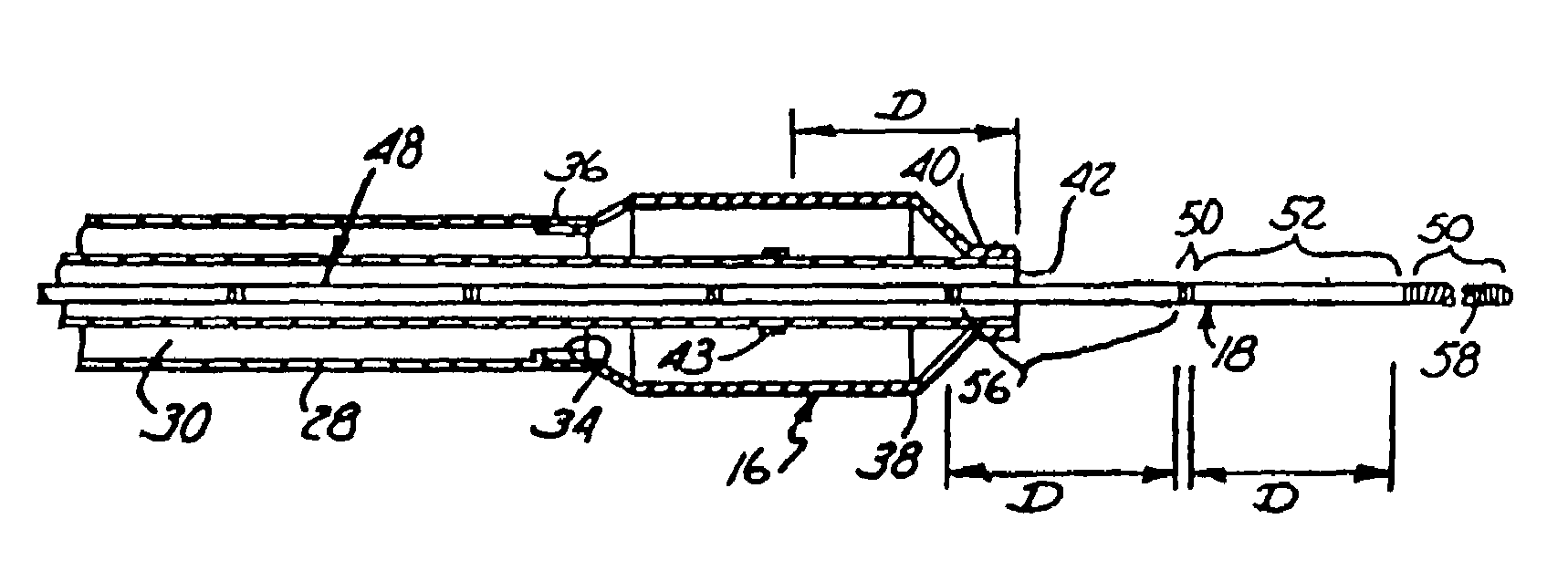
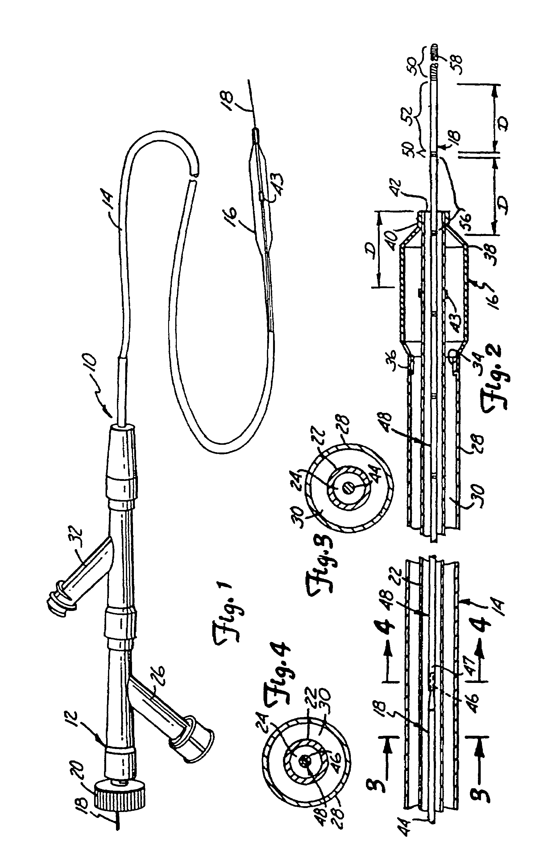
[0020]Catheter 10, as shown in FIGS. 1–4, is an over-the-wire balloon dilatation catheter which includes a manifold 12, a shaft 14, a balloon member 16 and a guide wire 18.

[0021]Manifold 12, defining a proximal portion of catheter 10, provides a means for introducing the guide wire 18 and inflation fluid for the balloon member 16 into the shaft 14. A thumb screw 20 is threadably mounted on a proximal end of manifold 12 for use in fixing the position of guide wire 18 relative to the manifold 12, shaft 14 and balloon member 16.

[0022]The shaft 14 has an inner tube 22 (see FIG. 2), which is preferably formed from a plastic material such as polyimide, and is attached to the manifold 12 to extend distally therefrom and define a guide wire lumen 24 for the guide wire 18. An inner surface of the inner tube 22 is coated with a lubricious material, such as polytetrafluoroethylene, to facilitate movement of the guide wire 18 therethrough.

[0023]The manifold 12 has a dye injection port 26 betwee...


PUM


Abstract

An over-the-wire balloon catheter has a radiopaque marker thereon at a known distance from a distal end of the catheter. An elongated flexible guide wire has a plurality of longitudinally spaced radiopaque markers on a distal portion thereof, with adjacent markers on the guide wire being longitudinally spaced at a distance equal to the known distance between the distal end of the catheter and its radiopaque marker. The guide wire is advanced through an artery until one of its markers is positioned at a desired location relative to a stenosis. Subsequently, the balloon catheter is advanced over the guide wire until the radiopaque marker of the catheter is in a predetermined position relationship to the radiopaque marker of the guide wire which has aligned on the stenosis. The cooperating radiopaque markers of the guide wire and catheter thus allow the balloon member of the catheter to be positioned relative to the stenosis in a timely fashion without the need to constantly inject fluoroscopic dye to view the stenosis.

Description

[0001]This application is a continuation of application Ser. No. 08 / 673,674, filed Jun. 26, 1996, now U.S. Pat. No. 6,179,788; which in turn is a continuation of application Ser. No. 07 / 969,047, filed Oct. 30, 1992, now abandoned; which in turn is a continuation of application Ser. No. 07 / 452,710, filed Dec. 19, 1989, now U.S. Pat. No. 5,209,730.BACKGROUND OF THE INVENTION[0002]1. Field of the Invention[0003]The present invention relates to the field of angioplasty and in particular, to new and improved catheters for performing balloon angioplasty procedures on blood vessels.[0004]2. Description of the Prior Art[0005]Angioplasty has gained wide acceptance in recent years as an efficient and effective method for treating vascular diseases. Angioplasty is widely used in the treatment of stenosis within the coronary arteries, although it has been used for the treatment of stenosis in other areas of the vascular system.[0006]The most widely used method of angioplasty makes use of a dila...

Claims


Application Information

Patent Timeline
IPC IPC(8): A61B5/00A61M25/00A61B5/103
CPCA61M25/09A61M2025/09166
Inventor SULLIVAN, DANIEL J.
Owner BOSTON SCI SCIMED INC
Why Eureka
Try Eureka