Apparatus and method employing an optical fiber for closed-loop feedback detection of arcing faults

a technology of optical fiber and closed-loop feedback, applied in the direction of optical radiation measurement, emergency protective arrangements for limiting excess voltage/current, instruments, etc., can solve the problems of arcing fault inside the enclosure, unintended arcing fault, high energy gas, etc., and achieve the effect of large surface area

Active Publication Date: 2006-04-25
EATON INTELLIGENT POWER LTD
View PDF10 Cites 42 Cited by
  • Summary
  • Abstract
  • Description
  • Claims
  • Application Information

AI Technical Summary

Benefits of technology

[0021]The component of an electric power system may include an enclosure housing a switchgear bus bar. The enclosure may include a surface facing the switchgear bus bar. The optical fiber may include an outer jacket, an inner fiber and an opening in the outer jacket at the gathering portion. The optical fiber at the gathering portion may be formed as a spiral and may be fastened to the surface of the enclosure. The opening in the outer jacket at the gathering portion may be opposite the surface and proximate the switchgear bus bar to receive the some of the light at a first predetermined wavelength and the some of the light from another source. This allows for distributing light sensing over a relatively large surface area. This reduces the potential for shielding, blocking or covering the sensing areas.

Problems solved by technology

At times, however, unintended arcing faults can occur within switchgear cabinets, such as between power buses, or between a power bus and a grounded metal component.
Such arcing faults can produce high energy gases which pose a threat to the structure and nearby personnel.
Frequently, a worker inadvertently shorts out the power bus, thereby creating an arcing fault inside the enclosure.
The resulting arc blast creates an extreme hazard and could cause injury or even death.
This problem is exacerbated by the fact that the enclosure doors are typically open for maintenance.
This has been done at great additional costs due to the heavy gauge metal used and numerous weld joints needed to prevent flying debris.
Even with these precautions, the blast from an arcing fault inside the switchgear cannot be contained.
The pressure sensing method is limited by the insensitivity of the pressure sensors.
By the time cabinet pressure has risen to detectable levels, the arcing fault has already caused significant damage.
Thus, merely detecting light at about 520 nm will not distinguish an arcing fault from these other sources.
If an arcing fault develops in the bus bar compartment, then the light from the fault is injected into, or interferes with, the optical fiber conductor through its jacket.
Although there is an increased danger that the optical fiber conductor may be destroyed, the destruction will occur after the fault has been detected.
The resulting short on the power bus causes an upstream circuit breaker to clear the fault.

Method used


Image

  • Apparatus and method employing an optical fiber for closed-loop feedback detection of arcing faults
  • Apparatus and method employing an optical fiber for closed-loop feedback detection of arcing faults
  • Apparatus and method employing an optical fiber for closed-loop feedback detection of arcing faults

Examples


Embodiment Construction

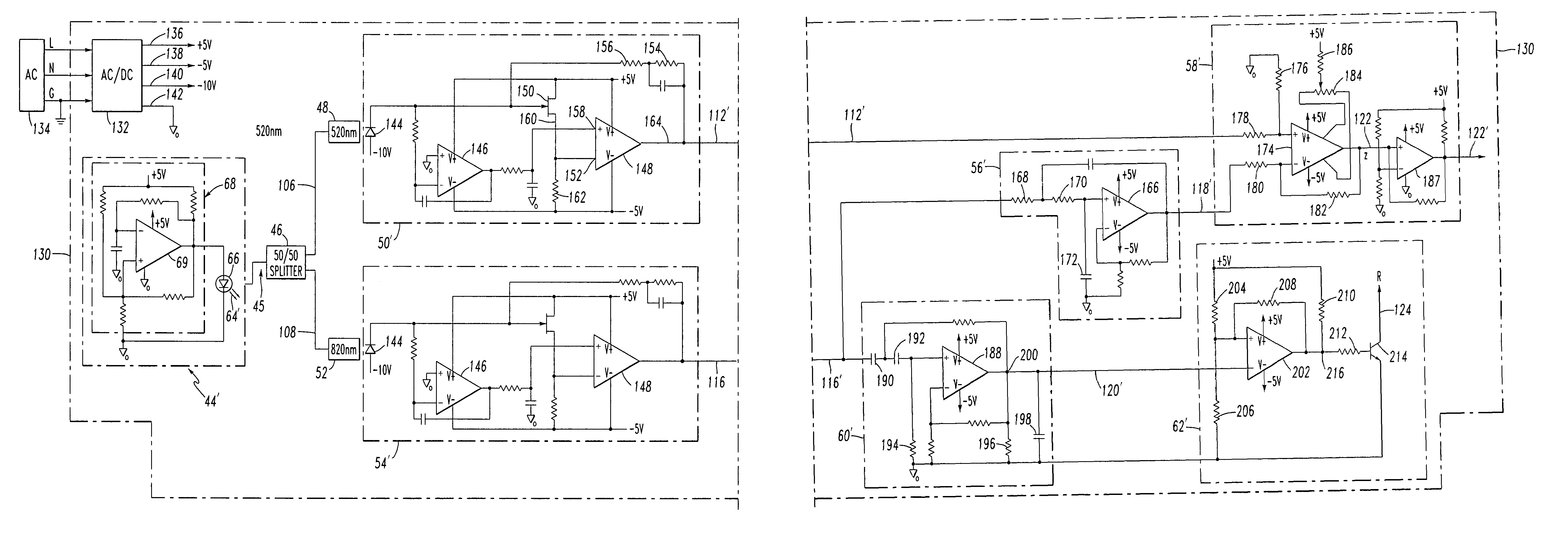
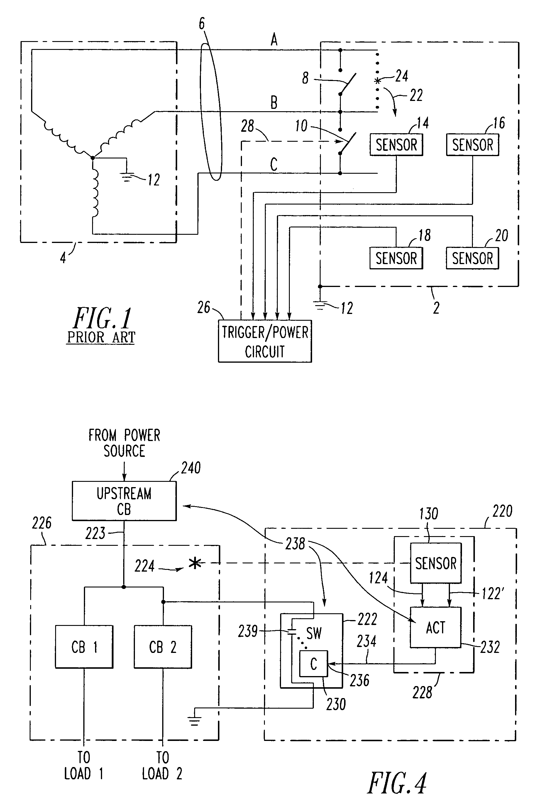
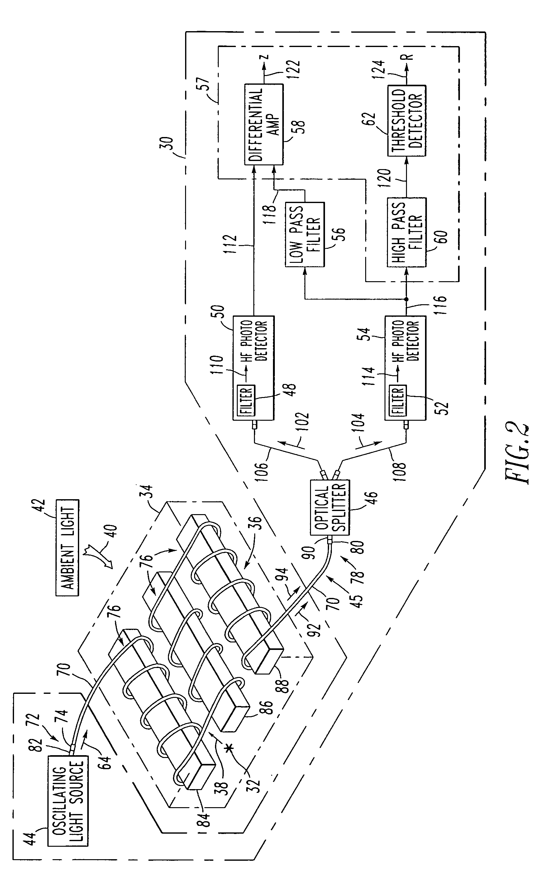
[0035]Referring to FIGS. 2 and 6, an arcing fault light sensor 30 detects an arcing fault 32 at an electric power system component, such as switchgear 34 including a three-phase power bus 36. Although three-phase switchgear 34 is disclosed, the invention is applicable to a wide range of electric power system components (e.g., low voltage systems (e.g., motor circuit protectors, load panels, bus runs); medium voltage fuse panels; single phase systems; capacitor banks; navy ship board applications) that are susceptible to arcing faults.

[0036]As is typical, the arcing fault 32 generates arc light 38 at a first predetermined wavelength (e.g., about 520 nm, in this example) in the presence of light 40 at one or more second different wavelengths (e.g., about 820 nm, in this example) from another source, such as ambient light 42. Although ambient light 42 is shown, the light 40 may originate from a wide range of sources (e.g., tungsten bulb light; flashlight; fluorescent light; flash bulb ...


PUM


Abstract

An apparatus detects arcing faults at a first wavelength. A light source provides modulated light at a second different wavelength and a first frequency. An optical fiber receives the modulated light and gathers ambient light at both wavelengths. A splitter receives and splits the received light into first and second beams. A first filter extracts from the first beam a first filtered beam including the first wavelength. A first photodetector generates a first electrical signal from the first filtered beam. A second filter extracts from the second beam a second filtered beam excluding the first wavelength. A second photodetector generates a second electrical signal from the second filtered beam. A low pass filter extracts from the second electrical signal a third electrical signal representative of light at the second wavelength excluding the modulated light. A comparator generates an arcing signal when the first electrical signal exceeds the third electrical signal.

Description

BACKGROUND OF THE INVENTION[0001]1. Field of the Invention[0002]The present invention relates to the detection of arcing faults at components of electric power systems and, more particularly, to detecting such faults within the metal cabinets of switchgear. More specifically, the invention relates to an apparatus and method for detecting arcing faults with optical fibers.[0003]2. Background Information[0004]Electric power systems incorporate switches for control and protection purposes. Distribution systems, which form part of the overall electric power system, include main and branch power buses and circuit breakers mounted in metal cabinets to form switchgear. Interruption of current flow in the buses of the distribution system by a circuit breaker creates an arc as the contacts of the circuit breaker open. These arcs caused by interruption are contained and extinguished in the normal course of operation of the circuit breaker.[0005]At times, however, unintended arcing faults can ...

Claims


Application Information

Patent Timeline
Patent Type & Authority Patents(United States)
IPC IPC(8): H02H3/00H02B13/065H02H1/00
CPCH02H1/0023
Inventor SHEA, JOHN J.
Owner EATON INTELLIGENT POWER LTD
Why Eureka
Try Eureka