
Link transmission control with common time reference

a transmission control and time reference technology, applied in the field of link transmission control with common time reference, can solve the problems of not being able to guarantee or limit the end-to-end delay and jitter, and the fidelity of real-time streams at the points of reception is significantly reduced, so as to achieve the effect of increasing robustness and independen

Inactive Publication Date: 2006-04-25
SYNCHRODYNE
View PDF7 Cites 16 Cited by
  • Summary
  • Abstract
  • Description
  • Claims
  • Application Information

AI Technical Summary

Benefits of technology

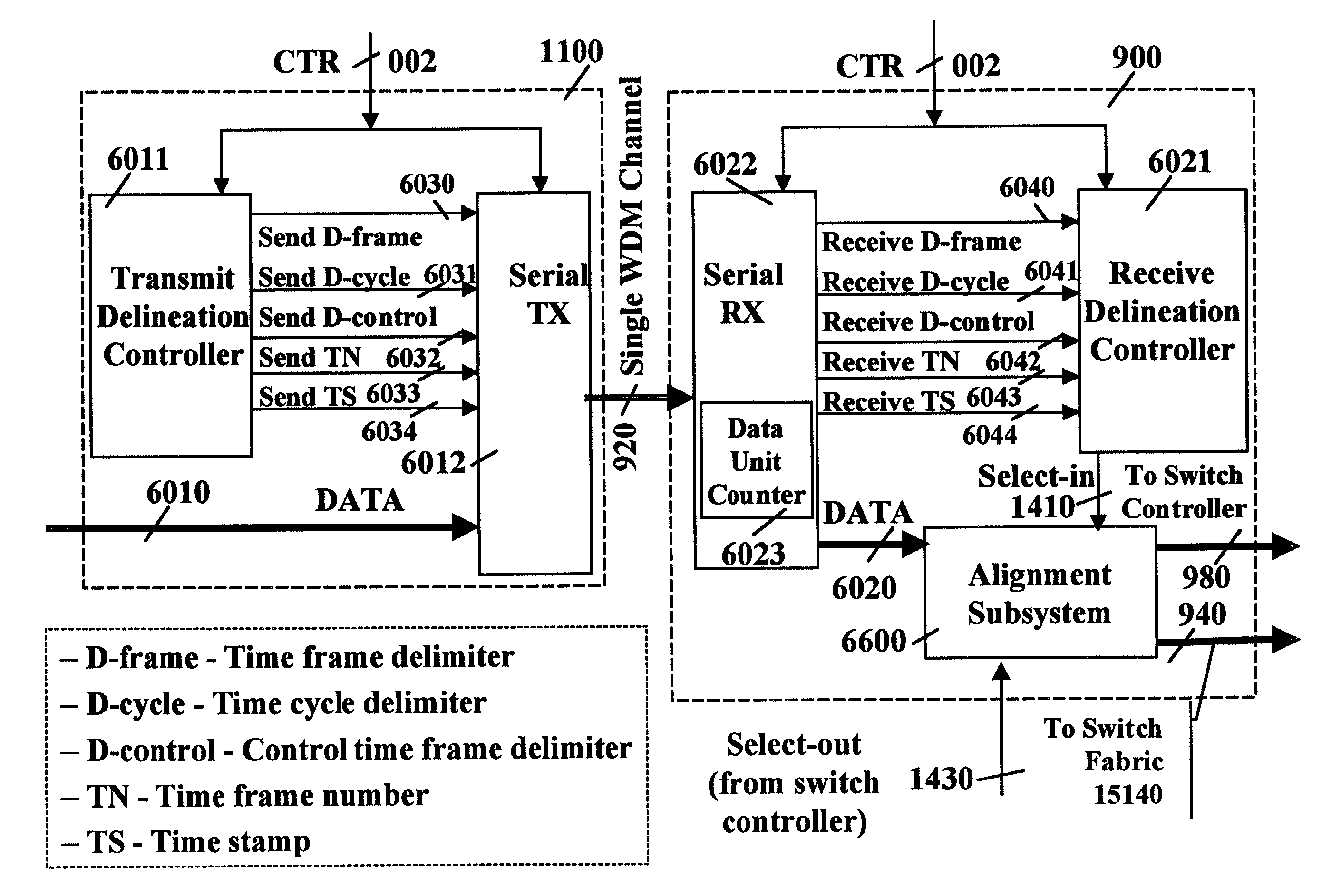
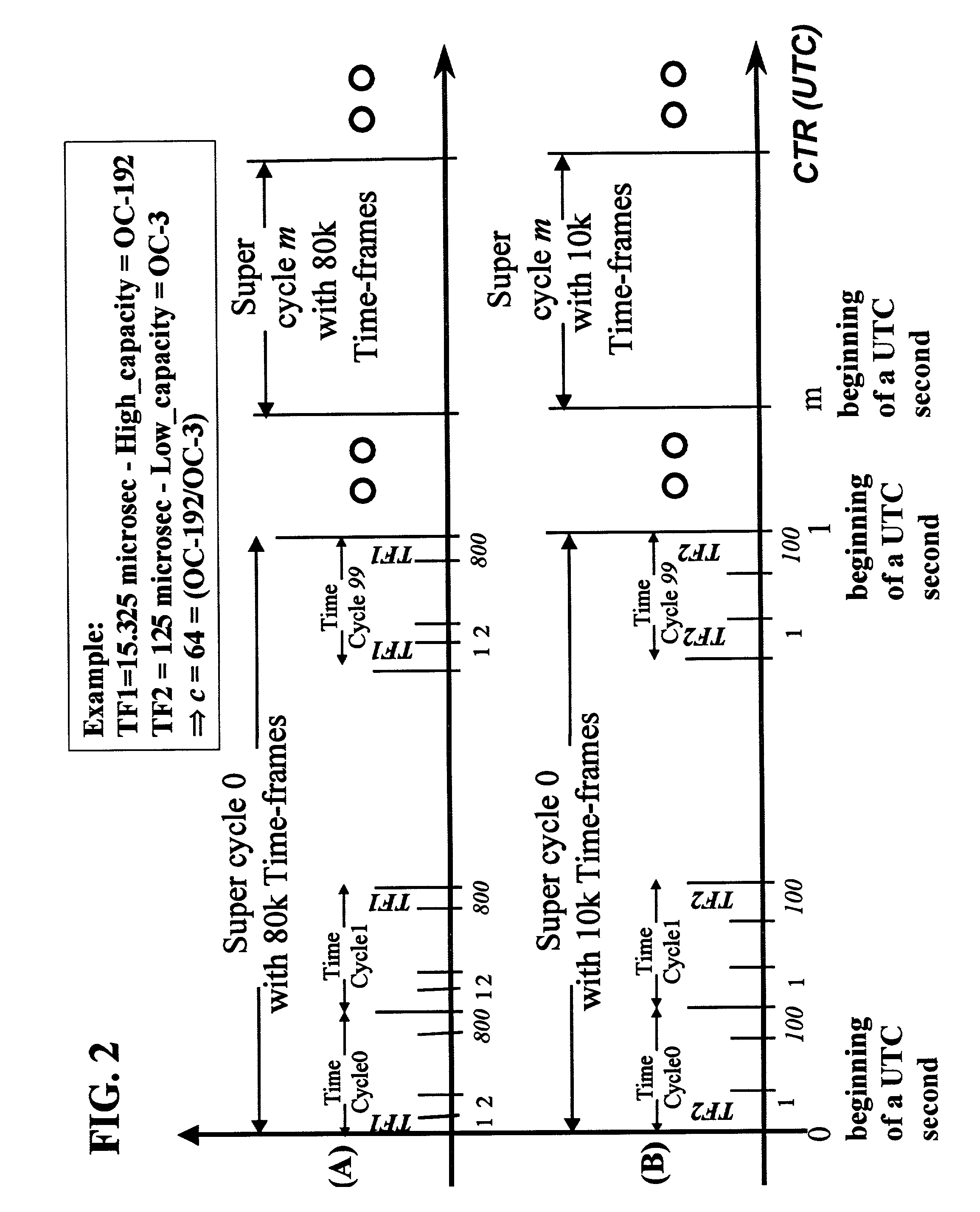
[0048]A method is provided for coupling control information with selected time frames. Such control information is used by coupled transmitting systems and receiving systems to identify at least one of the boundaries of the time frames, the ordinal number of the time frame within the ordinal number of the time cycle within the super cycle. Deployment of this method enables the requirement on the accuracy of the common time reference to be relaxed and thereby increases the robustness and reliability of the switching systems operating responsive to the common time reference.
[0050]Coupling control information with each time frame enables an increase in the reliability of the switching system and a reduction in the accuracy requirement on the common time reference signal. Moreover, one aspect of the invention comprises methods for providing protection switching by pre-allocating protection channels. In a possible embodiment, the same protection channel is shared by a plurality of primary channels. In an alternative embodiment, a protection channel carries low priority traffic while the primary channel operates normally.
[0052]The method for switching with different time references provides the switching systems with an increased robustness and independence with regards to the availability of an external common time reference signal.

Problems solved by technology

Circuit-switching networks, currently the main carrier for real-time traffic, are designed for telephony service and cannot be easily enhanced to support multiple services or carry multimedia traffic in their native data unit formats.
However, current packet switches and routers operate asynchronously and provide “best effort” service only, in which end-to-end delay and jitter are neither guaranteed nor bounded.
Statistical variations of traffic intensity often lead to congestion that results in excessive delays and loss of packets, thereby significantly reducing the fidelity of real-time streams at their points of reception.
Additionally, current packet switches and routers electronically process the header of each packet to be routed and switched, which requires high processing power and limits the scalability of the packet switching network.
This is in contrast to circuit switching, where (1) there are time slot slips, and (2) deterministic pipeline forwarding is not possible.
Yemini's invention has another problem, which is congestion, that is the direct result of using “sink” trees.
The lack of pipeline forwarding leads to the above mentioned scheduling and congestion problems.
Such problems are due to the fact that incoming time bands of Yemini's invention are not aligned in different input ports of the network's switches.
Furthermore, Yemini's et al. patent does not specify what are the temporal relationship of the same and different time bands on different “sink” tree switches when the link propagation delay and the end-to-end propagation delay are not zero.
However, switching of whole lambdas (e.g., lambdas at OC-192) is inefficient and costly for three reasons:1. N square problem: the number of lambdas needed to accommodate all the possible connections among all access points is on the order of the square of the number of such access points.
This will limit the size of the optical core.2. Bandwidth mismatch problem: there is a substantial bandwidth mismatch when extremely high capacity backbone packet networks feed low capacity access links.
As data leaves the core and is moved by packet switches towards the edge, buffers at access links frequently become congested, causing increased delays and dropped packets.3. Traffic unbalancing problem: the traffic load across the network is not evenly distributed, i.e., it is not balanced.
Thus, trying to satisfy the traffic load requirements using whole lambda_switching is both inflexible and inefficient.
This operation complexity is comparable to that of a T1 multiplexer.
Though highly efficient, a Banyan Network is subject to what is known as switch blocking: it may be impossible to connect an idle input with an idle output because a switching element is not available on the path between input and output.
The advances in optical transport led to the realization of high speed optical channels; however, a single source transmitting to a single destination will not fill such a channel.
However, taking full advantage of such advances for dynamic optical switching is not obvious for several reasons: (i) Processing of in band control information (e.g., packet headers) is not possible; (ii) Dynamic optical storage is not available to assist in coping with switch control and reconfiguration time; and (iii) Optical switch reconfiguration time should be significantly smaller than the time between two successive reconfigurations.
Due to the above limitations it is not possible to realize an asynchronous optical packet switching system, and therefore, using time is necessary.
However, time-based techniques deployed in circuit switching—e.g., SONET, based on byte switching (i.e., byte de-multiplexing and byte multiplexing)—are not applicable to all-optical switches.

Method used


Image

  • Link transmission control with common time reference
  • Link transmission control with common time reference
  • Link transmission control with common time reference

Examples


first embodiment

[0480]The objective of the clocking subsystem 16900 is to produce an LTR signal 310 synchronized with the CTR signal 002, whenever present. When the CTR signal 002 is not available, if at least two of the UTR signals 16320a, 16320b, and 1632c from their respective mapping controllers 16440 have the same frequency, the LTR signal 310 generated by the clocking system 16900 is synchronized with the isochronous UTR signals among 16320a, 16320b, and 1632c.

[0481]The clock controller 16910 receives as input the CTR signal 002 and the UTR signals 16320a, 16320b, and 1632c of the various input links from their respective mapping controllers 16440. If the CTR signal 002 is available, the clock controller 16910 uses it as the target signal 16915, i.e., connects its CTR input 002 with its target signal output 16915.

[0482]If the CTR signal 002 is not available, the clocking subsystem 16900 tries to devise the CTR from one of its neighboring nodes. The first step is for the clock controller 169...

second embodiment

[0484] if an external CTR signal 002 is not available, the clock controller 16910 of the clocking system 16900 in FIG. 35 executes the reference node election algorithm presented in FIG. 32, and described above, to identify a node in the network whose LTR should be used as a CTR and to select one of the neighboring switching systems from whose UTR the LTR is to be derived.

[0485]The input counter 16930 and the output counter 16935 are incremented with a frequency generated by a clock 16920 on the increment control signal 16925. The input counter 16930 is reset with the frequency of the target signal 16915. Thus, before each reset, the input counter 16930 contains the duration, according to the clock 16920, of the last time frame as defined by the target signal 16915.

[0486]The purpose of the FIR filter 16950 is to smooth the fluctuations of the measurement 16933 of the duration of each time frame by providing as output 16955 a time frame duration obtained by averaging the measured dur...


PUM


Abstract

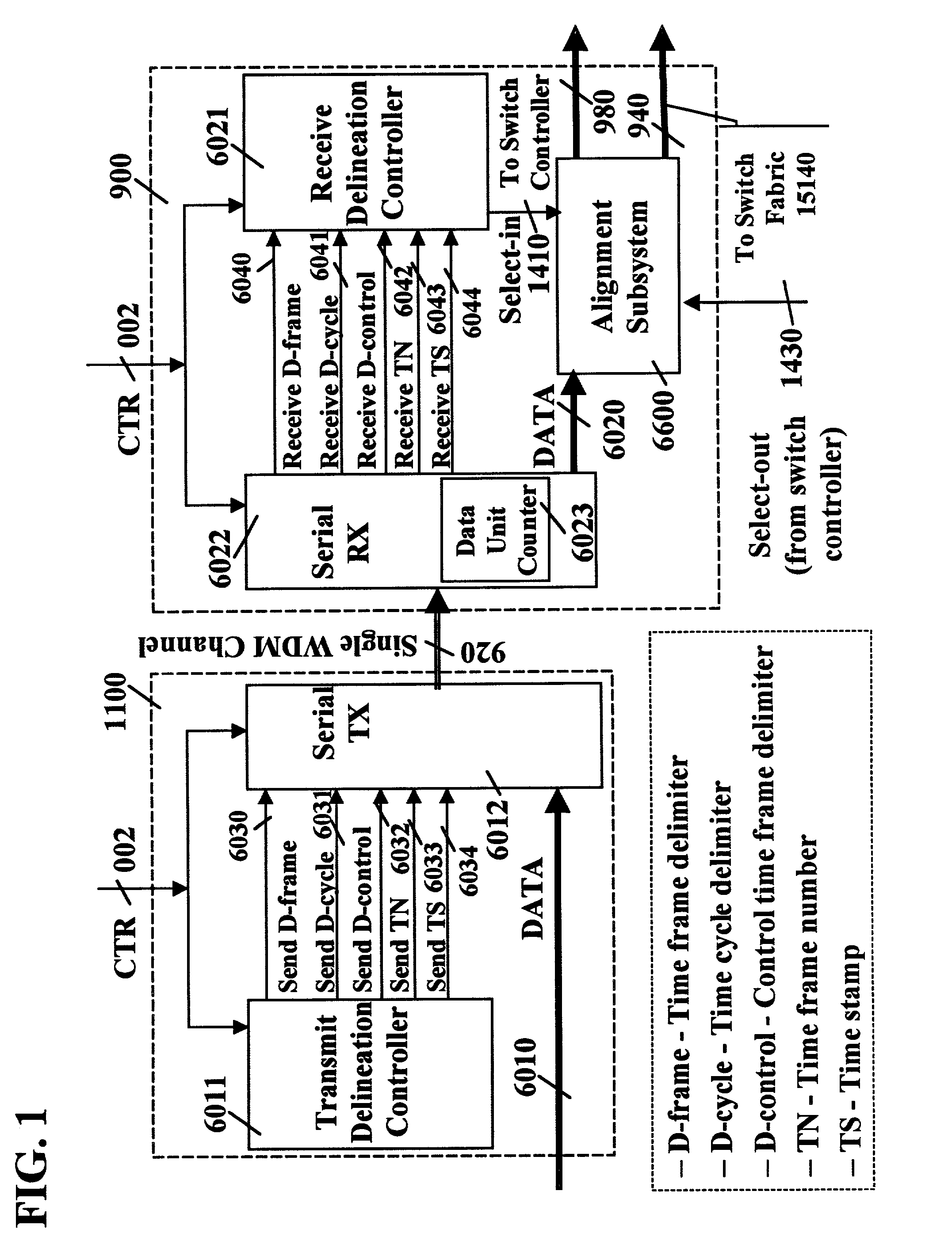
This invention specifies how control information is inserted in the flow of data units on a channel between two common time reference (CTR) driven switches in order to delineate time frames, sub-time frames, and time cycles. The delineation enables the receiver to unambiguously associate the received data units with time frame, sub-time frame, and time cycles. The invention further introduces a method for counting data units in order to, among other things, detect the end of a time frame, the end of a time cycle, and the position and value of other control information.

Description

RELATED APPLICATIONS[0001]This is a continuation-in-part application, under 37 C.F.R. §5.53, of pending prior application Ser. No. 09 / 120,700, filed on Jul. 22, 1998, now U.S. Pat. No. 6,377,579 for “INTERCONNECTING A SYNCHRONOUS SWITCHING NETWORK THAT UTILIZES A COMMON TIME REFERENCE WITH AN ASYNCHRONOUS SWITCHING NETWORK,” and further claims priority of pending provisional application Ser. No. 60 / 235,765, filed on Sep. 27, 2000, for “SWITCHING, GROOMING, AND DEGROOMING METHODS AND LINK TRANSMISSION CONTROL WITH COMMON TIME REFERENCE,” and of pending provisional application Ser. No. 60 / 261,133, filed on Jan. 10, 2001, for “SWITCHING METHODS WITH COMMON TIME REFERENCE AND PLURALITY OF TIME FRAME DURATIONS.”FEDERALLY SPONSORED RESEARCH OR DEVELOPMENT[0002]Not Applicable.BACKGROUND OF THE INVENTION[0003]This invention relates generally to a method and apparatus for switching and grooming of data units, over a plurality of communications links with a plurality of transmission rates, in...

Claims


Application Information

Patent Timeline
IPC IPC(8): H04J3/06H04J3/00H04L12/56H04L12/64H04L29/06H04Q11/00H04Q11/04
CPCH04L12/6418H04L29/06H04L47/10H04L47/22H04L47/28H04L47/283H04L49/3063H04L49/55H04Q11/0062H04Q11/0478H04J3/0644H04L69/28H04J2203/0082H04J2203/0083H04L49/254H04L49/30H04L49/3009H04L2012/5624H04L2012/5674H04Q2011/0033H04Q2011/0045H04J3/0685H04L9/40
Inventor OFEK, YORAMBALDI, MARIO
Owner SYNCHRODYNE
Learn More