Method and apparatus for fuel/air preparation in a fuel cell

Active Publication Date: 2006-05-02
APTIV TECH LTD
View PDF26 Cites 34 Cited by
  • Summary
  • Abstract
  • Description
  • Claims
  • Application Information

AI Technical Summary

Benefits of technology

[0009]A catalytic reformer and method for fast start-up is provided. The reformer includes a reactor having an inlet for receiving a flow of fuel and a flow of air, a reforming catalyst disposed within a reforming chamber in the reactor for converting the fuel and air to a reformate stream, and an outlet for discharging the produced reformate stream. An ignition device is disposed within the reactor for initiating an exothermic reaction between the fuel and air. Heat generated thereby warms the catalyst to provide fast light-off of the reformer, and also warms the wall of the reactor adjacent the catalyst. An associated control system selects fuel and air flow delivery rates and operates the ignition device to achieve fast light-off of the reforming catalyst at start-up and to maintain the catalyst at a temperature sufficient to optimize reformate yield. The system operates at a lean fuel/air mixture during ignition and combustion mode, then switches over to a rich fuel/air mixture durin

Problems solved by technology

A problem in the past has been how to elevate the temperature of the catalyst quickly in order to begin generating reformate in the shortest possible time.
A problem still exists, however, in how to rapidly and uniformly vap

Method used


Image

  • Method and apparatus for fuel/air preparation in a fuel cell
  • Method and apparatus for fuel/air preparation in a fuel cell
  • Method and apparatus for fuel/air preparation in a fuel cell

Examples


Embodiment Construction

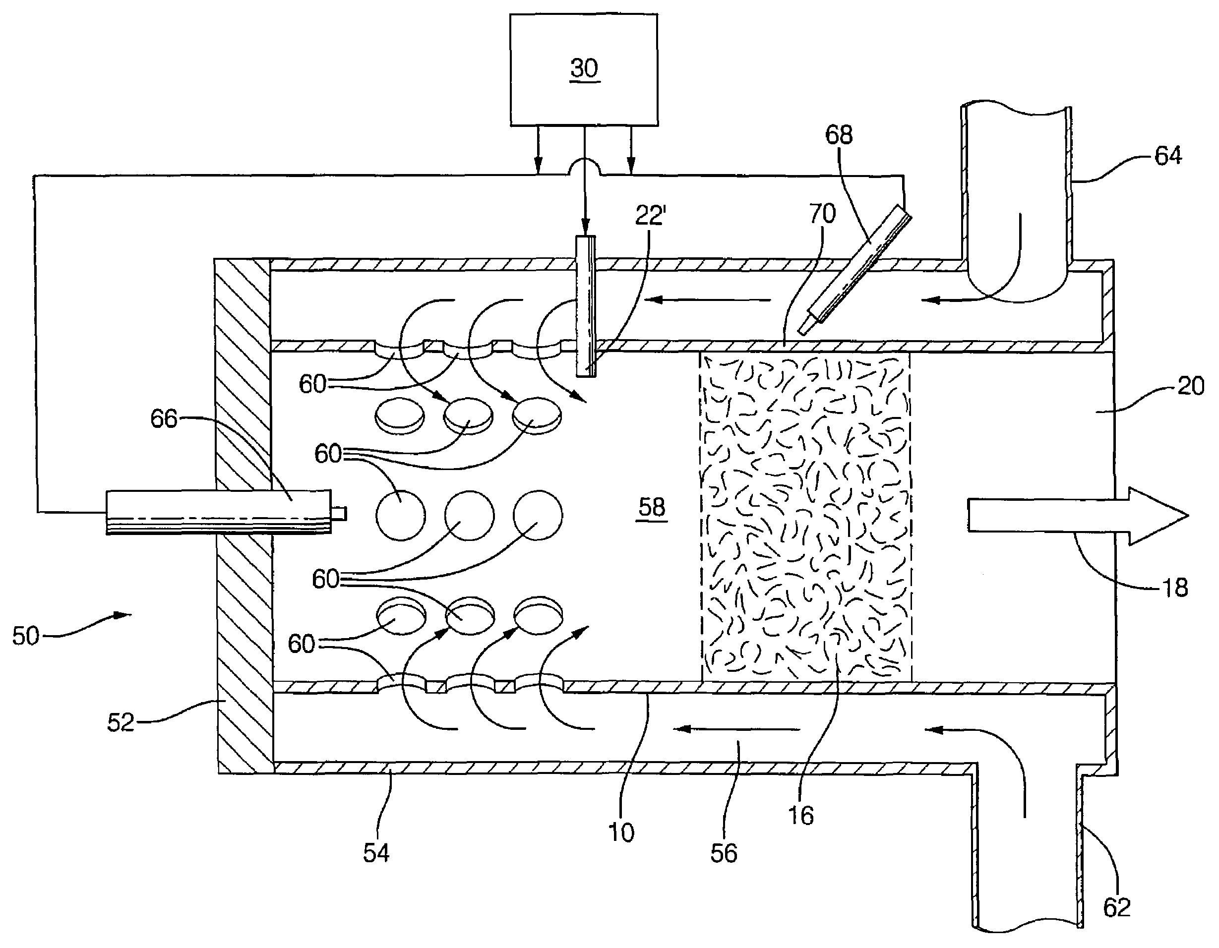
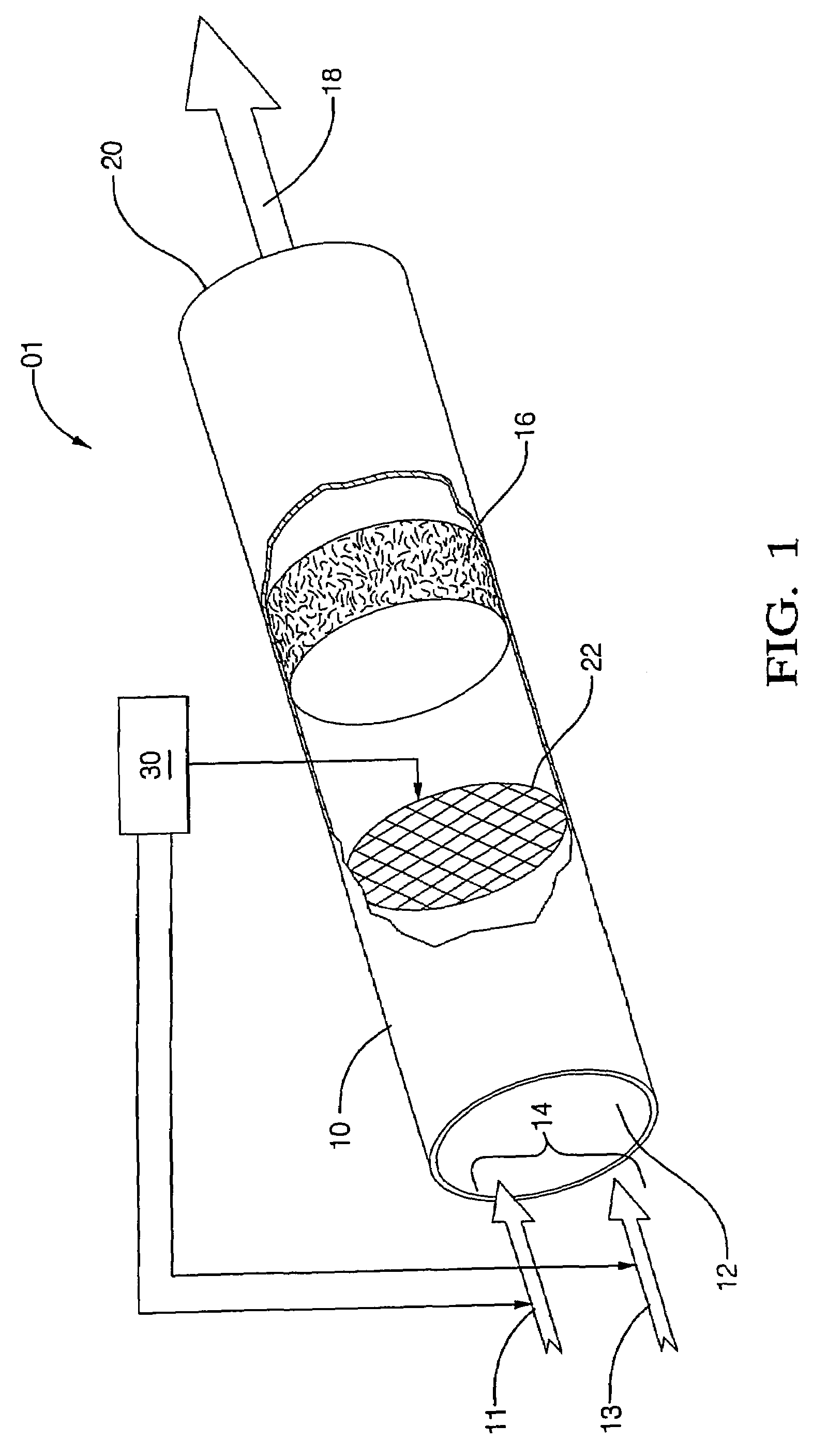
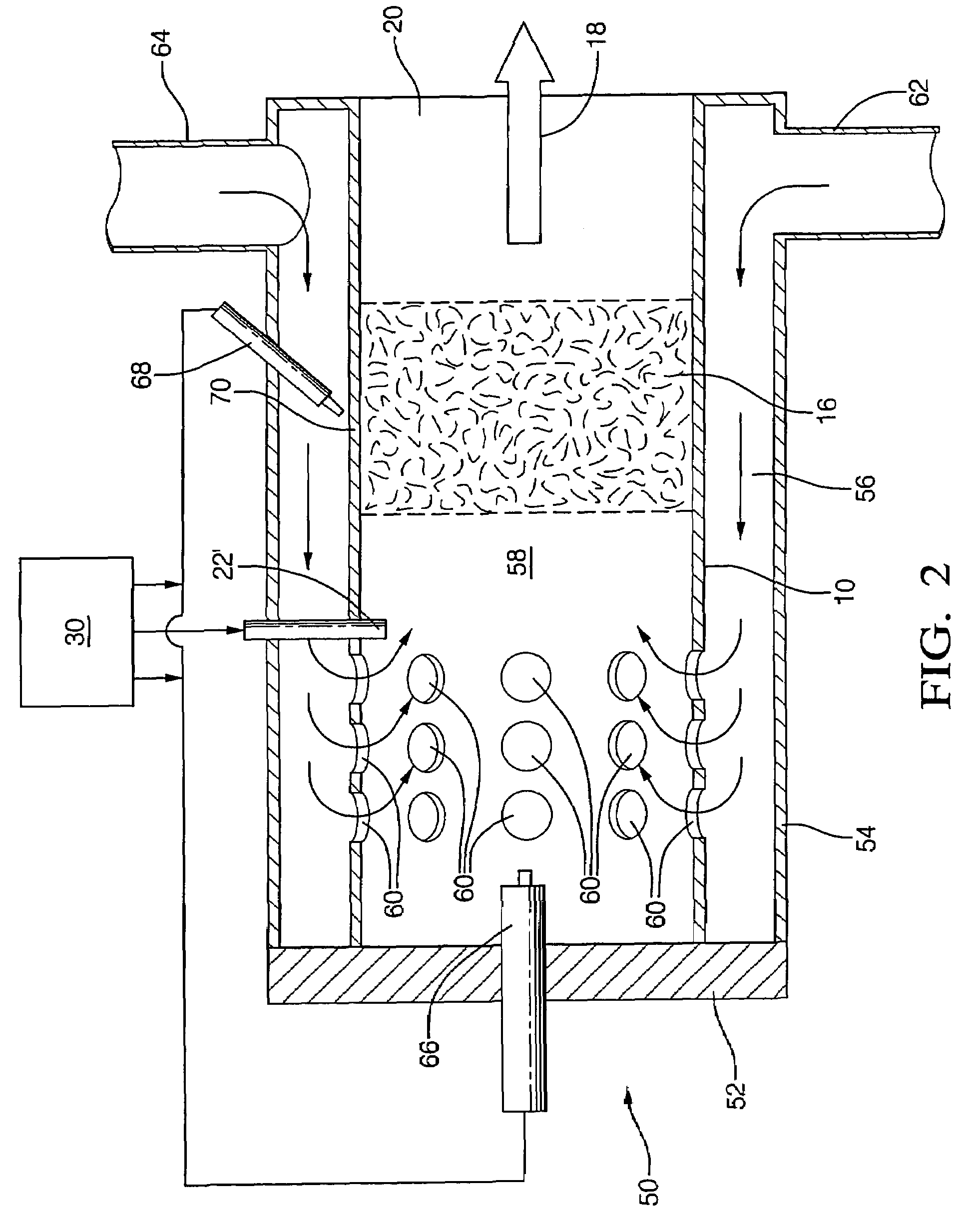
[0013]Referring to FIG. 1, a fast light-off catalytic reformer 01 includes a reactor 10 having an inlet 12 in a first end for receiving a flow of fuel 11 and a flow of air 13, shown as combined fuel-air mixture 14. Reactor 10 may be any shape, but preferably comprises a substantially cylindrical reactor tube. While the present description discusses a single reactor 10, reforming catalyst 16, and ignition device 22, the present fast light-off reformer may comprise more than one reactor, as desired.

[0014]Reforming catalyst 16 is disposed within reactor 10 and may comprise any reforming catalyst material suitable for converting the fuel feedstock and air to reformate, including, but not limited to, for example, rhodium, platinum, their alloys, and combinations thereof. Preferably, a protective coating or firewall (not shown) is disposed about catalyst 16. During operation, a fuel-rich mixture comprising air and a liquid hydrocarbon fuel such as natural gas, light distillates, methanol,...


PUM

PropertyMeasurementUnit
Timeaaaaaaaaaa
Timeaaaaaaaaaa
Poweraaaaaaaaaa

Abstract

A fast start-up catalytic reformer for producing hydrogen-rich reformate from hydrocarbon fuel includes a reactor having an inlet for receiving a flow of fuel and a flow of air, a reforming catalyst disposed within a reforming chamber in the reactor, and an outlet for discharging the produced reformate stream. An ignition device within the reactor tube ignites a first lean mixture in combustion mode to generate exhaust gases to warm the catalyst which also warms the wall of the reactor adjacent the catalyst. The reactor then switches over to a rich fuel/air mixture during reforming mode. A jacket concentrically surrounds the reactor, defining a mixing chamber therebetween which communicates with the reforming chamber via openings in the wall of the reactor. Fuel entering the reformer in combustion mode is injected directly into the reforming chamber to provide rapid warming of the catalyst. Fuel entering the reformer in reforming mode is sprayed onto the outside of the reactor in the mixing chamber, preferably in the heated region of the tube for very rapid vaporization.

Description

CROSS-REFERENCE TO RELATED APPLICATIONS[0001]The present application claims priority from U.S. Provisional Patent Application of the same title, Ser. No. 60 / 390,962, filed Jun. 24, 2002.TECHNICAL FIELD[0002]The present invention relates to a catalytic reformer and method for converting a hydrocarbon stream to a reformate fuel stream comprising hydrogen; more particularly, to a fast light-off catalytic reformer and method for rapid production of reformate for hydrogen coldstart in an internal combustion engine; and most particularly, to an improved method and apparatus for rapid vaporization and mixing of fuel and air upon entry into the reformer. The present invention is useful for providing reformate to a fuel cell, and especially a solid oxide fuel cell.BACKGROUND OF THE INVENTION[0003]A catalytic hydrocarbon fuel reformer converts a fuel stream comprising, for example, natural gas, light distillates, methanol, propane, naphtha, kerosene, gasoline, diesel fuel, or combinations the...

Claims


Application Information

Patent Timeline
IPC IPC(8): C10K3/06C10J3/00B01J8/02C01B3/32C01B3/38H01M8/06H01M8/12
CPCB01J8/0221B01J8/0285C01B3/323C01B3/386H01M8/0618H01M8/0631B01J8/0278Y02E60/525B01J2208/00407B01J2208/00415B01J2208/00716C01B2203/0261C01B2203/066C01B2203/0811C01B2203/1064C01B2203/1217C01B2203/1223C01B2203/1241C01B2203/1247C01B2203/1276C01B2203/1604C01B2203/1619C01B2203/169H01M8/0662H01M2008/1293H01M2250/20Y02T90/32Y02E60/50Y02T90/40
Inventor DAUER, KENNETH J.SALEMI, MICHAEL R.NASHBURN, RICHARD F.KIRWAN, JOHN
Owner APTIV TECH LTD
Why Eureka
Try Eureka