Motor driving device

Inactive Publication Date: 2006-05-02
DENSO CORP
View PDF16 Cites 40 Cited by
  • Summary
  • Abstract
  • Description
  • Claims
  • Application Information

AI Technical Summary

Benefits of technology

[0017]According to a tenth aspect of the present invention, the loss of the semiconductor switching element can be reduced while keeping the air blowing power of th

Problems solved by technology

For example, in a fan motor driving device for supplying a desired voltage to a fan motor mounted in a vehicle by driving a semiconductor switching element in the PWM mode, the semiconductor switching element is overheated when the temperature of the environment surrounding the driving device is abnormally increased or the load torque of

Method used


Image

  • Motor driving device
  • Motor driving device
  • Motor driving device

Examples


first embodiment

[First Embodiment]

[0026]A first embodiment according to the present invention will be described hereunder with reference to FIGS. 1 to 3.

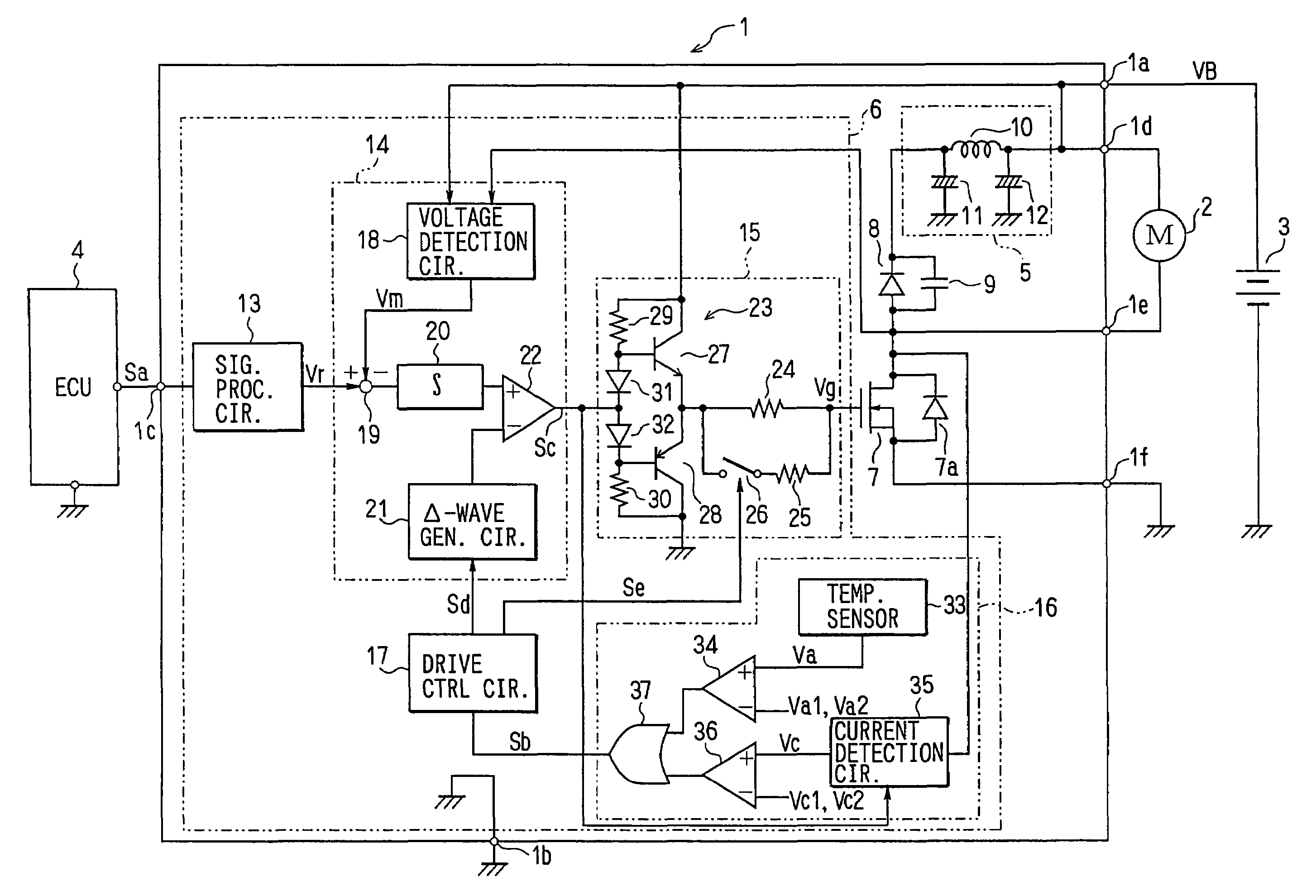
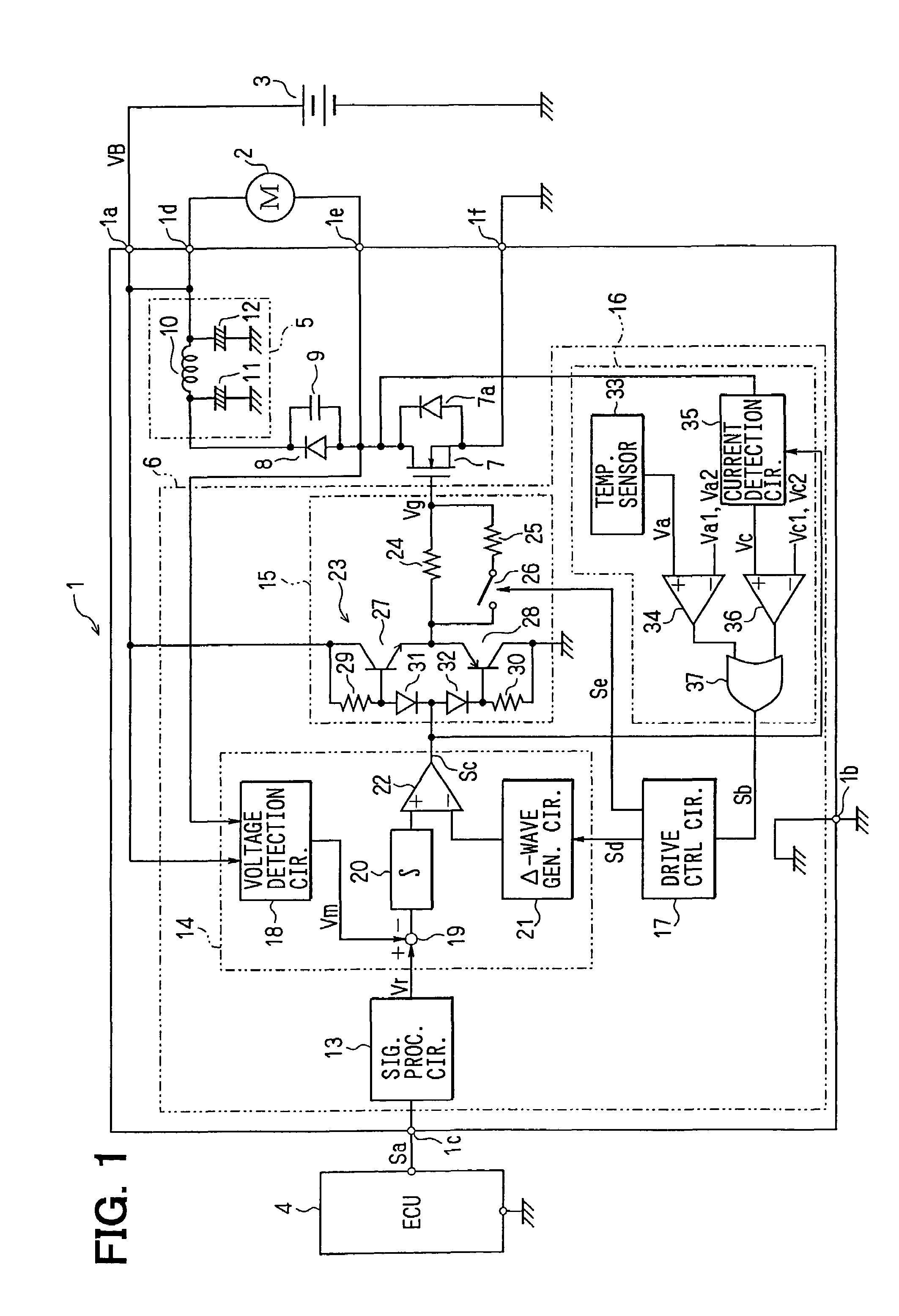
[0027]FIG. 1 shows the electrical construction of a motor driving device. A motor driving device 1 drives an air blowing fan motor 2 (hereinafter referred to as “motor 2”) for a heat exchanger in a cooling system for a vehicle, and it operates with a battery voltage supplied as a power supply voltage VB from a battery 3 to terminals 1a, 1b thereof. An instruction-signal Sa is supplied from an engine ECU 4 (Electronic Control Unit) to a terminal 1c. This instruction signal Sa is the digital data corresponding to a voltage to be applied to the motor 2 or an analog voltage signal.

[0028]ECU 4 concentrically carries out plural control operations relevant to an engine such as fuel injection control, ignition timing control, idle rotational speed control, etc. As not shown, ECU 4 is supplied with a temperature signal of engine cooling water, an ON / OFF sig...

second embodiment

(Second Embodiment)

[0067]Next, a second embodiment according to the present invention will be described with reference to the circuit diagram of FIG. 4. In FIG. 4, the same constituent elements as FIG. 1 are represented by the same reference numerals. A motor driving device 38 shown in FIG. 4 is different from the motor driving device 1 shown in FIG. 1 in that the construction of the overheat detecting circuit 39.

[0068]The overheat detecting circuit 39 is equipped with a power supply voltage detecting circuit 40 (corresponding to the power supply voltage detecting unit) for dividing the power supply voltage VB input to the terminal 1a and then detecting the voltage thus divided. The voltage Vb corresponding to the power supply voltage VB is input to the non-inverting input terminal of the comparator 36, and threshold voltages Vb1, Vb2 are input to the inverting input terminal of the comparator 36. The threshold voltages Vb1, Vb2 correspond to the power supply voltages VB1, VB2 (VB1>...

third embodiment

(Third Embodiment)

[0071]FIG. 5 shows the electrical construction of the motor driving device according to a third embodiment of the present invention. The same constituent elements as FIG. 1 are represented by the same reference numerals. The motor driving device 41 shown in FIG. 5 is different from the motor driving device 1 shown in FIG. 1 in the construction of an overheat detecting circuit 42. That is, the overheat detecting circuit 42 is equipped with a duty ratio detecting circuit 43 for detecting the duty ratio of the PWM signal Sc. The voltage Vd corresponding to the duty ratio is input to the non-inverting input terminal of the comparator 36, and threshold voltages Vd1, Vd2 are input to the inverting input terminal of the comparator 36. The threshold voltages Vd1, Vd2 correspond to the duty ratios D1, D2 (D1>D2). The motor driving device 41 may be equipped with a current detecting circuit for detecting current flowing in the MOS transistor 7 for over-current protection.

[007...


PUM


Abstract

A temperature sensor (33) detects the temperature of a MOS transistor (7), and a current detecting circuit (35) detects current flowing in the MOS transistor (7). When the voltage corresponding to the detected temperature or the voltage corresponding to the detected current is increased to a threshold value or more, an overheat state detecting signal and further switching signal is set to a high level. As a result, a switch circuit in a driving circuit (17) is turned on, and the gate resistance value becomes the parallel value of a resistor (25), and the PWM frequency in the PWM control circuit is lowered, whereby the switching loss of the MOS transistor (7) can be reduced under the state that the motor (2) is rotated.

Description

CROSS REFERENCE TO RELATED APPLICATION[0001]This application is based upon, claims the benefit of priority of, and incorporates by reference the contents of, Japanese Patent Application No. 2003-63644 filed on Mar. 10, 2003.FIELD OF THE INVENTION[0002]The present invention relates to a motor driving device for controlling a motor applied voltage by driving a semiconductor switching element in Pulse Width Modulation (PWM) mode.BACKGROUND OF THE INVENTION[0003]JP-A-8-37789 (Patent Document 1) discloses a control method for an AC motor in which a switching frequency is varied in accordance with the value of a smoothened DC power supply voltage, the rotational speed of the AC motor, a primary electrical angle frequency, the intensity of an output voltage to be supplied or the frequency value of the output voltage or output current. JP-A-10-229674 discloses a DC-DC converter for carrying out the control of reducing a switching frequency under an over-current condition. JP-A-2001-161065 d...

Claims


Application Information

Patent Timeline
IPC IPC(8): H02H7/08B60H1/32G05B5/00H02M1/00H02M1/08H02M1/34H02P7/29H02P7/291
CPCB60H1/00828B60H1/00428Y02T10/88
Inventor NAKAMURA, KOJINOMURA, MANABUYOSHIMURA, SATOSHI
Owner DENSO CORP
Why Eureka
Try Eureka