

Antenna, and communication device using the same
- Summary
- Abstract
- Description
- Claims
- Application Information
AI Technical Summary
Benefits of technology
Problems solved by technology
Method used
Image

Examples
exemplary embodiment 1
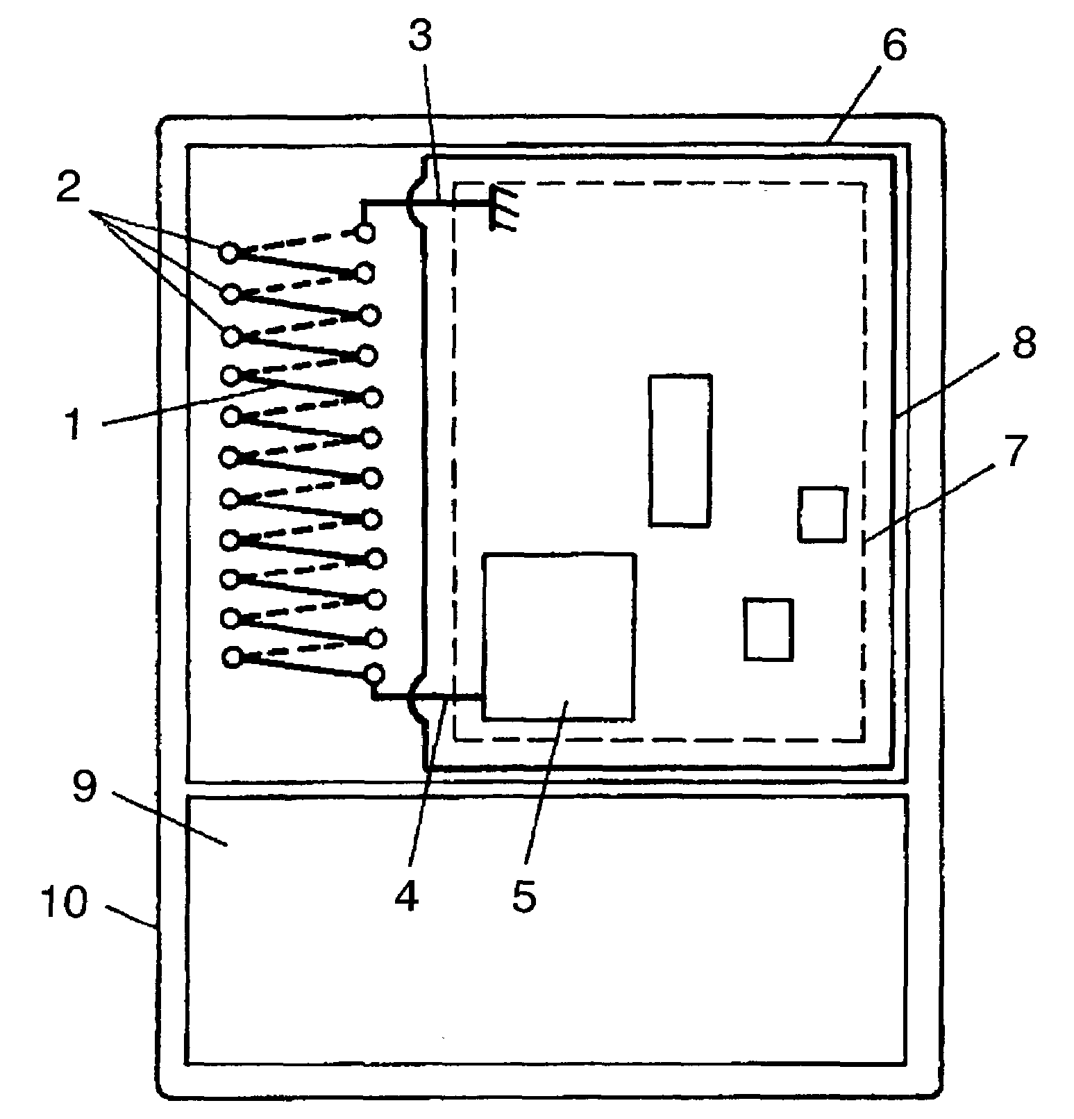
[0024]FIG. 1 illustrates a card-type communication device in accordance with exemplary embodiment 1 of the present invention. Base substrate 6 has one surface provided with ground 7 and the other surface having high frequency circuit 5 mounted thereon. Loop antenna 8 of about 100 turns surrounds ground 7 and high frequency circuit 5. Loop antenna 8 transmits and receives a low frequency signal. First radiator 1 having through-holes 2 and a helical conductive pattern printed on the surface of base substrate 6 is disposed with its central axis substantially in parallel to a side of ground 7. Thus, radiation gain of an antenna system can be improved since a magnetic dipole formed by first radiator 1 and a magnetic current induced at the ground of base substrate 6 have the same direction and are added. This card-type communication device may be used, for example, in a pocket of a shirt. Even in this case, the magnetic dipole formed by first radiator 1 and a magnetic current generated wi...
exemplary embodiment 2
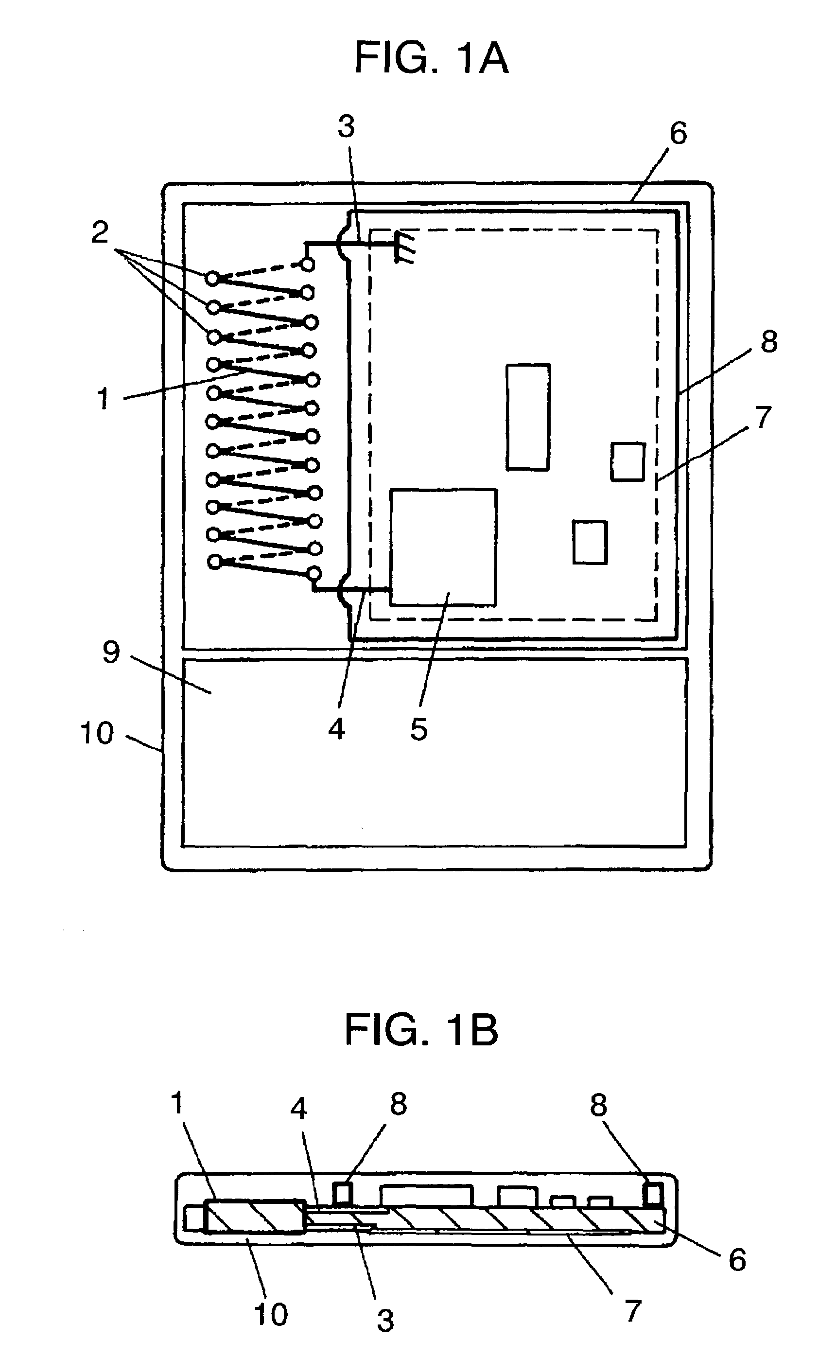
[0031]FIG. 2 illustrates a communication device in accordance with exemplary embodiment 2 of the present invention. First radiator 1 of helical shape is disposed at a side of base substrate 6 having an electronic circuit such as high frequency circuit 5 or the like mounted thereon. First radiator 1 has one end connected to high frequency circuit 5 with feeder 4, and the other end connected to a ground with short-circuiting line 3. In the vicinity of first radiator 1, meander-shaped second radiator 11 is disposed in insulated condition. The radiators widen a range of adjustable antenna impedance, whereby the antenna system is usable in two frequency bands. Meander-shaped second radiator 11, even if having a linear or helical shape, can exhibit the same characteristic.
[0032]Changing a pitch, element width and element length of the meander-shaped radiator allows the antenna impedance to be adjusted. By including the antenna formed in a conductive pattern on the substrate, the antenna s...
exemplary embodiment 3
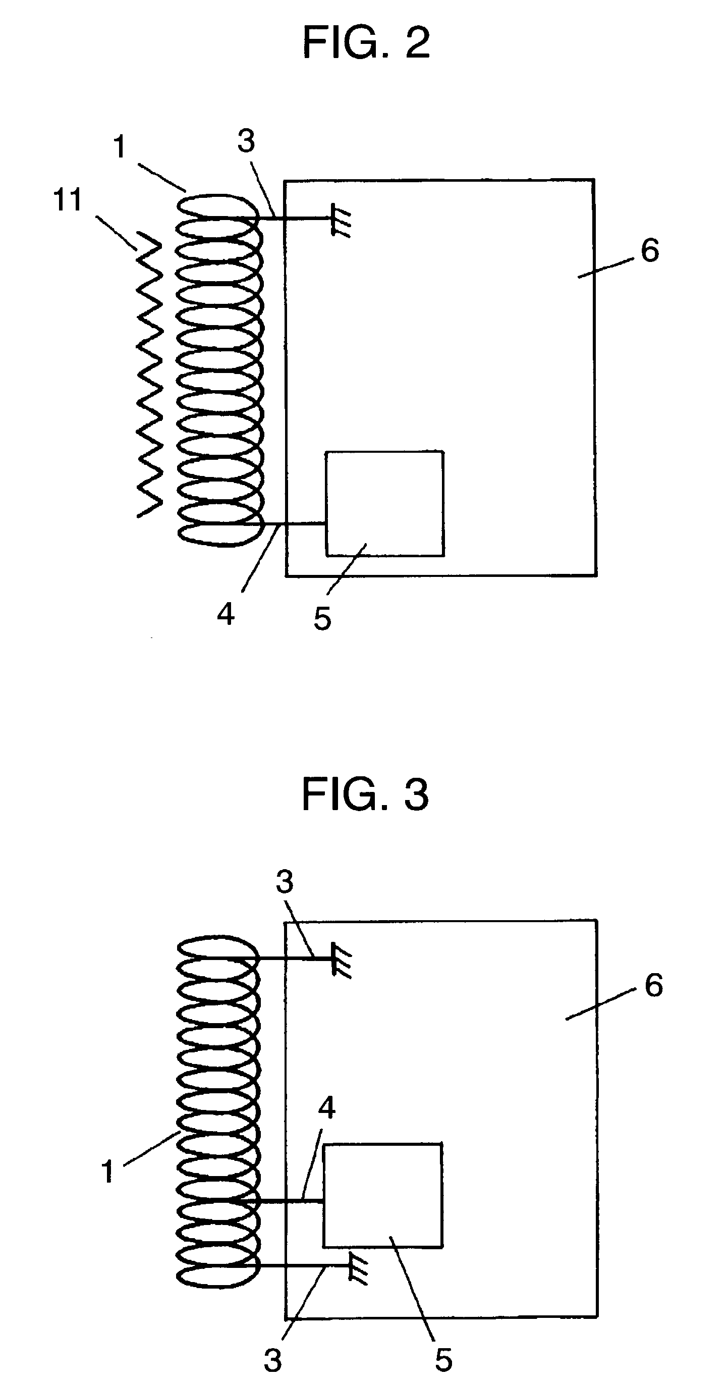
[0033]FIG. 3 illustrates a communication device in accordance with exemplary embodiment 3 of the present invention. First radiator 1 has both ends connected to a ground by short-circuiting line 3, and an arbitrary point, not being each end, connected to high frequency circuit 5 with feeder 4. A position of a connecting point of feeder 4 and first radiator 1 can adjust an antenna impedance close to 50Q, and thus provides the device with a satisfactory radiation characteristic without radiation loss caused by an element such as a matching circuit.
[0034]A short-circuiting element for connection to a ground of a metal case in the vicinity of a feeding part of an antenna enables impedance to be matched for a loop antenna with a low radiation resistance.
[0035]A communication device including the antenna system of embodiments 1 to 3, a controller for controlling transmission and reception of a signal, a drive unit for driving the controller, and a case for housing the antenna system, the c...
PUM
 Abstract
Description
Claims
Application Information