Eigen frequency detector for Sagnac interferometers

a technology of sagnac interferometer and eigen frequency detector, which is applied in the direction of speed measurement using gyroscopic effects, instruments, surveying and navigation, etc., can solve the problems of crystal oscillator drift, large testing area, accuracy limitations,

Active Publication Date: 2006-05-02
HONEYWELL INT INC
View PDF5 Cites 22 Cited by
  • Summary
  • Abstract
  • Description
  • Claims
  • Application Information

AI Technical Summary

Benefits of technology

[0011]This present invention proposes an improved method of detecting the eigen frequency, without the drawbacks associated with prior art methods. Specifically, employing the method according to the present invention does not require additional optical components, does not require imperfections in the phase modulator or the bias modulation, an

Problems solved by technology

This method has drawbacks in that it requires, among other things, extensive testing for calibration, and, since it is an indirect measurement of the eigen frequency, it has accuracy limitations.
However, the drift of the crystal oscillator over many years (e.g., 10 or greater) of operation is typically greater than what is required for high performance.
Furthermore, it is possible that the coil eigen frequency will significantly drift over many years due to aging effects of the fiber coil itself.
A drawback to this approach is that the sensitivity of the eigen frequency error signal to changes in eigen frequency depends on imperfections of an optical component, which may or may not be at an acceptable level and may vary drastically from unit to unit.
This method adds significant complexity to the optical circuit and introduces additional intensity modulation, which could generate other types of gyro errors.
Anoth

Method used


Image

  • Eigen frequency detector for Sagnac interferometers
  • Eigen frequency detector for Sagnac interferometers
  • Eigen frequency detector for Sagnac interferometers

Examples


Embodiment Construction

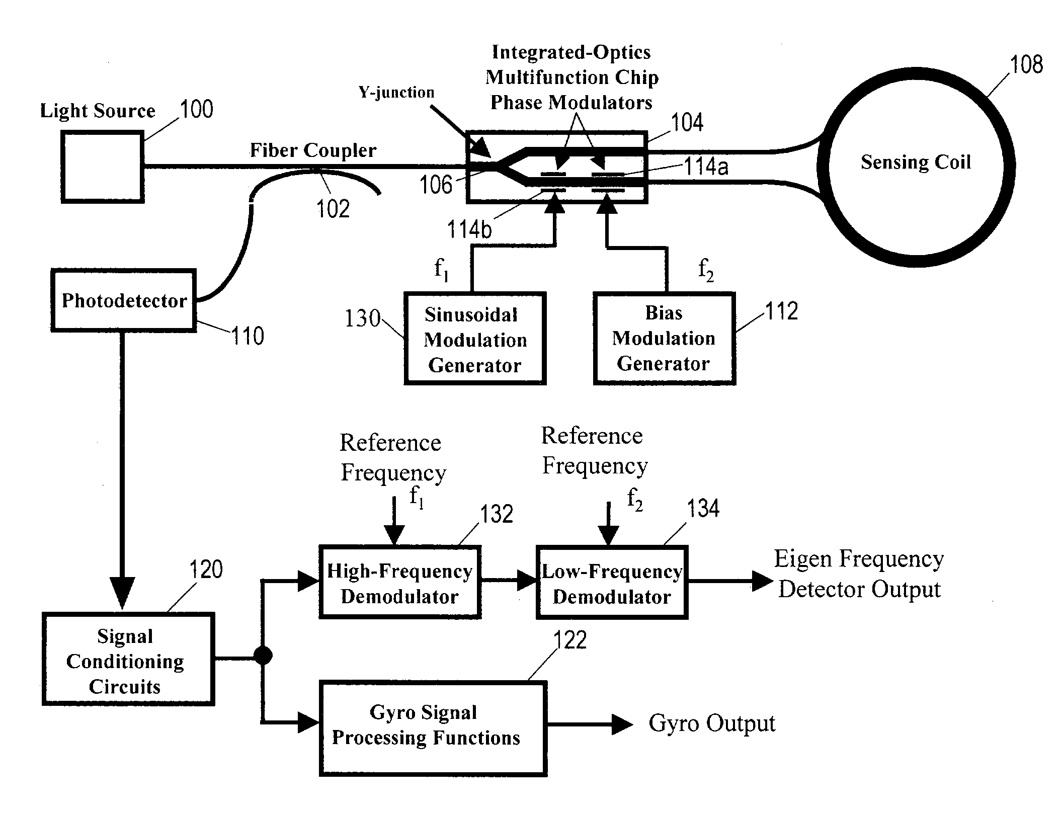
[0022]The present invention provides an improved method for detecting the coil eigen frequency during normal gyro operation. This improved method involves the use of an additional phase modulation applied to the light waves propagating through the sensing coil. The additional phase modulation generates an “error” signal that is proportional to the frequency difference between the gyro operating frequency and the eigen frequency. A servo loop controls the gyro operating frequency to the eigen frequency by driving the “error” signal to a null.

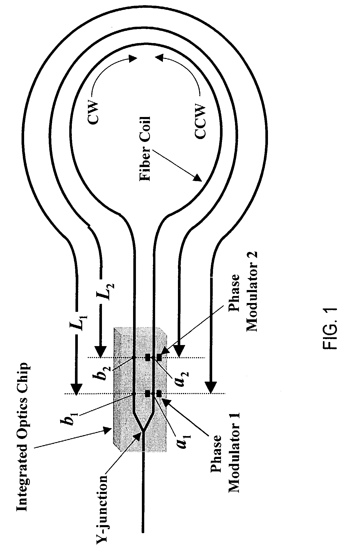
[0023]FIG. 1 shows a diagram of a sensing coil and an integrated optics chip with phase modulators to help describe the concept of an eigen frequency associated with a phase modulator. The entire optical loop comprises the optical path from the y-junction, through the integrated optics chip, through the fiber coil, and returning back through the integrated optics chip and to the y-junction. If a phase modulation is applied at point a1 within the ...


PUM


Abstract

A system for detecting the eigen frequency of a sensing coil in a fiber optic gyro (FOG) that includes a fiber coupler connected to the light source, an integrated optics chip (IOC) capable of modulating light received from the light source via the fiber coupler, a sensing coil in communication with the IOC, a first modulation generator for imparting a first modulation signal to the light, and a photodetector for receiving light returning from the sensing coil that is representative of a rotation rate of the sensing coil. Along with the foregoing there is provided a second modulation generator for imparting a second, preferably sinusoidal, modulation signal to the light, a high-frequency demodulator in communication with a signal produced, at least indirectly, by the photodector, and a low-frequency demodulator in communication with the high-frequency demodulator. The high-frequency demodulator receives the first modulation signal as a reference frequency and the low-frequency demodulator receives the second modulation signal as a reference frequency. An output of the low-frequency demodulator represents a magnitude and sign of a frequency difference between a frequency of the second modulation signal and an even-harmonic of the eigen frequency.

Description

BACKGROUND[0001]1. Field of the Invention[0002]The present invention relates generally to Sagnac interferometers and more particularly to detecting the eigen frequency of a sensing coil of a fiber optic gyroscope.[0003]2. Background of the Invention[0004]The eigen frequency (sometimes called the “proper” frequency) of a fiber optic gyroscope (FOG) sensing coil is an extremely important parameter for the operation of navigation and high performance grade FOGs. The eigen frequency is essentially defined by the optical path length of the sensing coil. Many sources of rate output errors are reduced or effectively eliminated by operating the bias modulation at the eigen frequency. Generally speaking, the bias modulation must be operated to within at least a few ppm of the eigen frequency in order for FOGs to meet high performance requirements. New applications are now putting more demanding performance requirements on these types of gyros.[0005]For navigation grade FOGs that must operate...

Claims


Application Information

Patent Timeline
IPC IPC(8): G01C19/64G01C19/72
CPCG01C19/721
Inventor STANDJORD, LEE K.DOHENY, DAVID A.
Owner HONEYWELL INT INC
Why Eureka
Try Eureka