Occlusion catheter for the ascending aorta

a technology for occlusion catheters and ascending aortas, which is applied in the field of occlusion catheters for ascending aortas, can solve the problems of occlusion catheters, hindering the blood flow to the lower limb, and obstructing blood flow, so as to improve the position retainability of occlusion catheters and excess rigidity

Inactive Publication Date: 2006-05-09
VAYU
View PDF16 Cites 22 Cited by
  • Summary
  • Abstract
  • Description
  • Claims
  • Application Information

AI Technical Summary

Benefits of technology

[0015]Wherefore, it is an object of the present invention to provide an occlusion catheter capable of obstructing the blood flow in the ascending aorta without inserting the same through the femoral artery.
[0016]Another object of the present invention is to provide an occlusion catheter capable of maintaining the condition where the balloon is placed in the proper indwelling position.

Problems solved by technology

The tube is inserted through the femoral artery and advanced through the thoracic aorta to the ascending aorta, in which the distal end of the tube is placed and the balloon is inflated, with the result that the blood flow is obstructed.
These conventional occlusion catheters, however, have the following problems: The conventional occlusion catheter to be inserted through the femoral artery may hinder the blood flow directed to the lower limb, particularly, of a patient whose blood vessel in the lower limb is thin.
In such a case an occlusion catheter of this type cannot be used.
As a result, a lumen to pass the guide wire therethrough must be provided in the tube, which leads to a relatively large diameter of the catheter and therefore a further factor of hindrance to the blood flow.
Furthermore, since the conventional occlusion catheter is long enough to extend from the femoral artery to the ascending aorta, the flow path resistance of the lumen in the tube is so large that the flow rate of the cardiac muscle protective drug cannot be easily increased.
Although the flow rate of the cardiac muscle protective drug can be increased by simply having a lumen of a larger inner diameter, such a lumen necessarily requires a catheter of a larger diameter, which may hinder the blood flow toward the lower limb.
When inserted through the femoral artery, the conventional occlusion catheter may have its balloon damaged in the case where the blood vessel in the lower limb or the aorta is calcified, or cannot be easily advanced through a meandering blood vessel.
While the tube preferably is flexible enough to curve to a certain extent for better operation in the blood vessel, the tube having an excessive flexibility cannot support the balloon which is pushed by the blood flow from a pump oxygenator or the infusion pressure of the cardiac muscle protective drug.
Thus, it is not easy to retain the balloon in the proper indwelling position.

Method used


Image

  • Occlusion catheter for the ascending aorta
  • Occlusion catheter for the ascending aorta
  • Occlusion catheter for the ascending aorta

Examples


first embodiment

[0051

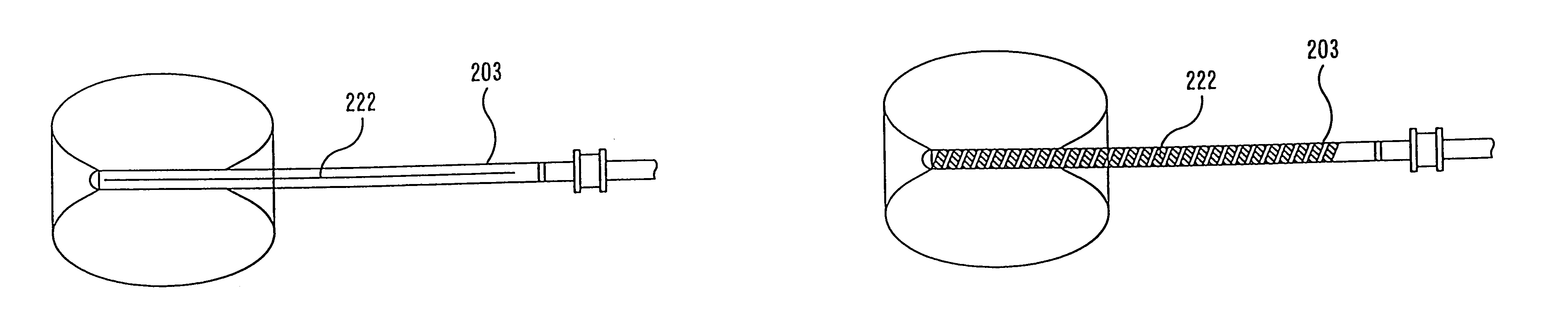
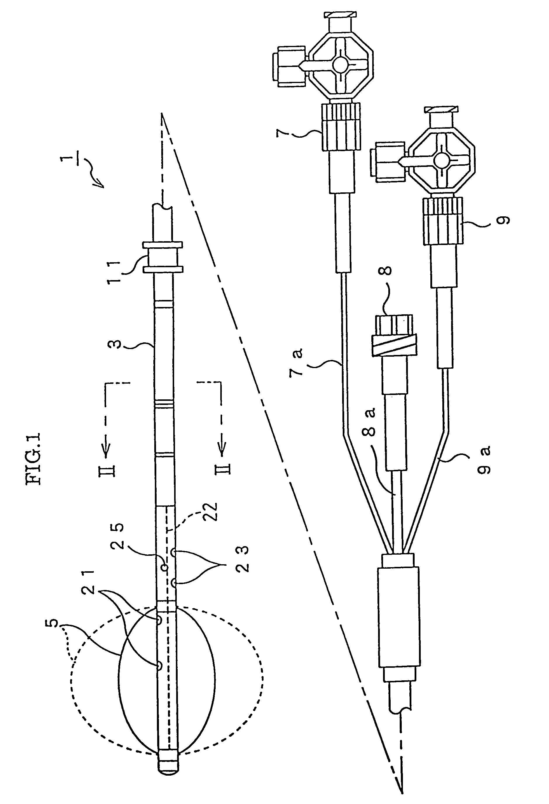
[0052]As shown in FIG. 1, an occlusion catheter for the ascending aorta 1 according to the present invention is provided with a catheter tube 3, a balloon 5, a first connector 7, a second connector 8, a third connector 9 and a tie cushion 11, etc.

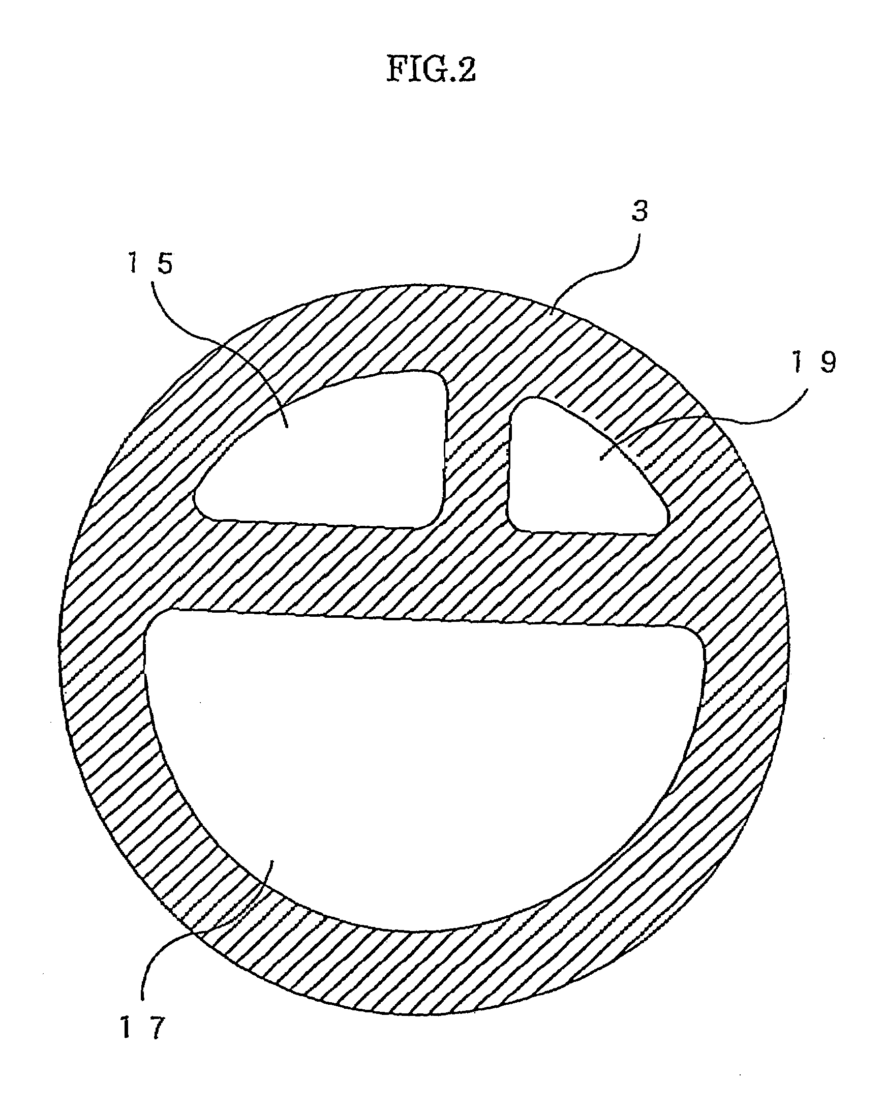
[0053]The catheter tube 3 made of polyurethane is long enough to include a portion with a length of 400 mm and an outer diameter of 3.6 mm which is insertable into a blood vessel. As shown in FIG. 2, a first lumen 15, a second lumen 17 and a third lumen 19 are formed separately from one another within the catheter tube 3.

[0054]The first lumen 15 has one end communicating with the first connector 7 through a first auxiliary tube 7a and the other end communicating with a plurality of inflation agent supply and drainage apertures 21 having a diameter of 1 mm and formed inside the balloon 5. The first lumen 15 is used as a path for guiding an inflation agent (e.g. a physiological salt solution) supplied from the first connector 7 side to t...

second embodiment

[0068

[0069]As shown in FIG. 6, an occlusion catheter 101 according to a second embodiment of the present invention is provided with a catheter tube 103, a balloon 105, a first connector 7, a second connector 8, a third connector 9 and a tie cushion 111, etc.

[0070]The catheter tube 103 made of polyurethane is long, and a first lumen 115 and a second lumen 117 are formed therein separately from each other as shown in FIG. 7A.

[0071]The first lumen 115 has one end communicating with the first connector 7 through a first auxiliary tube 7a (see FIG. 6) and the other end communicating with a plurality of inflation agent supply and drainage apertures 121 formed inside the balloon 105. The first lumen 115 is used as a passage for guiding an inflation agent (e.g. a physiological salt solution) supplied from the first connector 7 side to the inside of the balloon 105.

[0072]The second lumen 117 has one end communicating with the second connector 8 through a second auxiliary tube 8a, the other e...

third embodiment

[0094

[0095]In a third embodiment, a side aperture 325 for releasing the drug therefrom is provided in a catheter tube 303 in the position corresponding to the approximate center of a balloon 305, as shown in FIGS. 12A and 12B. The balloon 305 has concavities 331 and 332 on the outer surface when inflated in the same manner as in the second embodiment, and also has a depression in a part of the center portion of the balloon 305. The balloon 305 is joined to the catheter tube 303 within the depression and the concavities. At the bottom of the depression is provided the side aperture 325 for communicating the second lumen 317 with the outside of the catheter tube 303 (see FIG. 13). Since the other elements are similar to the elements in the first embodiment, particular description is omitted.

[0096]An occlusion catheter according to the present embodiment, as schematically illustrated in FIG. 13, is inserted into the ascending aorta as in the first and the second embodiments. An inflati...


PUM


Abstract

An occlusion catheter for the ascending aorta capable of obstructing the blood flow within the ascending aorta without inserting through the femoral artery. The occlusion catheter is provided with a drug release aperture formed in the region, which is closer to the proximal end of the catheter tube than a balloon on the outer circumference of the distal end and which is to be located in the vicinity of the coronary ostium when the balloon is placed within the ascending aorta. The present occlusion catheter, when inserted directly into the ascending aorta in the vicinity of the heart to obstruct the blood flow therewithin, enables delivery of a cardiac muscle protective drug to the vicinity of the coronary ostium without inserting the occlusion catheter through the femoral artery in the conventional manner.

Description

[0001]This is a Divisional of U.S. application Ser. No. 09 / 846,002 filed on Apr. 30, 2001, Now U.S. Pat. No. 6,679,861, which claims priority from Japanese Patent Application Ser. No. 2000-158152 filed May 29, 2000.BACKGROUND OF THE INVENTION[0002]i) Field of the Invention[0003]The present invention relates to an occlusion catheter for the ascending aorta used for obstructing the blood flow in the ascending aorta.[0004]ii) Prior Art[0005]When a cardiac surgery is performed, the blood flow in the ascending aorta is obstructed generally using a conventional cross-clamp through an opening in a patient's chest formed by thoracotomy.[0006]Recently, there have been attempts to obstruct the blood flow in the ascending aorta using an occlusion catheter for the ascending aorta (hereinafter referred to as “an occlusion catheter”) inserted through a femoral artery, for example, without performing an open chest operation.[0007]An occlusion catheter of this type comprises a tube and a balloon di...

Claims


Application Information

Patent Timeline
Patent Type & Authority Patents(United States)
IPC IPC(8): A61M29/00A61B17/00A61B17/12A61F2/958A61M25/00A61M29/02
CPCA61B17/12109A61B17/12136A61M25/003A61M25/1002A61M25/10A61B2017/00243A61M25/0029A61M25/0032A61M2210/127A61M2025/1052A61M2025/1056A61M2025/1095A61M2025/1097
Inventor YOZU, RYOHEITSUTSUI, NOBUMASAKUMENO, TAKASHI
Owner VAYU
Why Eureka
Try Eureka