Turbocharged engine control system

a control system and turbocharger technology, applied in the direction of electrical control, machine/engine, exhaust treatment electric control, etc., can solve the problems of engine operation conditions changing, and further promotion of clogging of particulate filters

Active Publication Date: 2006-05-16
NISSAN MOTOR CO LTD
View PDF8 Cites 20 Cited by
  • Summary
  • Abstract
  • Description
  • Claims
  • Application Information

AI Technical Summary

Benefits of technology

[0008]For example, when the particulate filter is used in a supercharged diesel engine equipped with turbo supercharger as in the above mentioned reference, the pressure in the vicinity of an inlet of the particulate filter increases when the pressure loss in the particulate filter increases as the particulate matter accumulates in the particulate filter over time. As a result, the efficiency of the turbo supercharger declines. Moreover, a volumetric efficiency declines and / or an internal exhaust recirculation increases since the back pressure of the engine increases. Thus, an engine output declines. In such a case, in order to maintain a desired output, the driver will unintentionally increase a depression amount of an accelerator pedal to increase an accelerator opening degree by an amount the engine output declined. Accordingly, a fuel injection quantity will be increased and an air-fuel ratio will be reduced. Thus, the particulate matter in the exhaust gas increases as the internal exhaust gas recirculation increases, and thus, the clogging of the particulate filter is further promoted. The clogging of the particulate filter promotes the increase of the particulate matter in the exhaust gas as explained above. As a result, the clogging of the particulate filter progresses rapidly.
[0009]Moreover, when the turbo supercharger is a variable-capacity turbo supercharger in which an opening degree of a nozzle of the exhaust turbine is variably controlled, the opening degree of the nozzle is set to a relatively smaller degree in response to an increase in pressure in the vicinity of the inlet of the particulate filter caused by the clogging in order to compensate for the reduction in the amount of fresh air. Thus, the pressure in the vicinity of the inlet of the exhaust turbine (i.e., the back pressure of the engine) increases further and the internal exhaust gas recirculation increases. As a result, a vicious cycle of declining engine output and depressing the accelerator pedal to compensate the engine output is further promoted.
[0010]In view of the above, one object of the present invention is to provide a turbocharged engine control system for an engine equipped with a variable-capacity turbo supercharger and an exhaust gas after-treatment system such as a particulate filter that prevents a progress of chain-reaction clogging of the particulate filter by appropriately controlling the engine and the turbo supercharger in response to the clogging, i.e., increase in pressure loss in the particulate filter.

Problems solved by technology

It has been discovered that when a particulate filter is used as in the above mentioned reference, a problem of pressure loss in the particulate filter occurs as the particulate matter accumulates in the particulate filter, which results in a clogging of the particulate filter.
Especially, the clogging of the particulate filter may cause engine operation conditions to change, and as a chain reaction, the clogging of the particulate filter may be further promoted.
As a result, the efficiency of the turbo supercharger declines.
Moreover, a volumetric efficiency declines and / or an internal exhaust recirculation increases since the back pressure of the engine increases.
Thus, an engine output declines.
Thus, the particulate matter in the exhaust gas increases as the internal exhaust gas recirculation increases, and thus, the clogging of the particulate filter is further promoted.
As a result, the clogging of the particulate filter progresses rapidly.

Method used


Image

  • Turbocharged engine control system
  • Turbocharged engine control system
  • Turbocharged engine control system

Examples


Embodiment Construction

[0033]Selected embodiments of the present invention will now be explained with reference to the drawings. It will be apparent to those skilled in the art from this disclosure that the following descriptions of the embodiments of the present invention are provided for illustration only and not for the purpose of limiting the invention as defined by the appended claims and their equivalents.

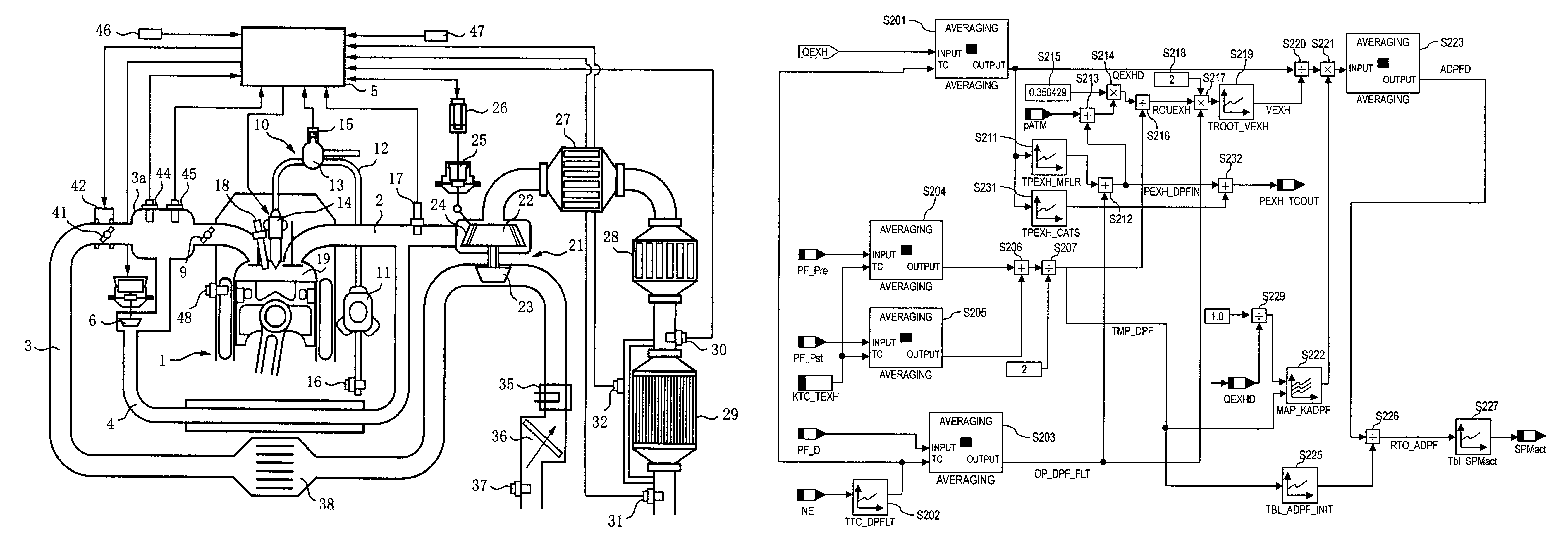
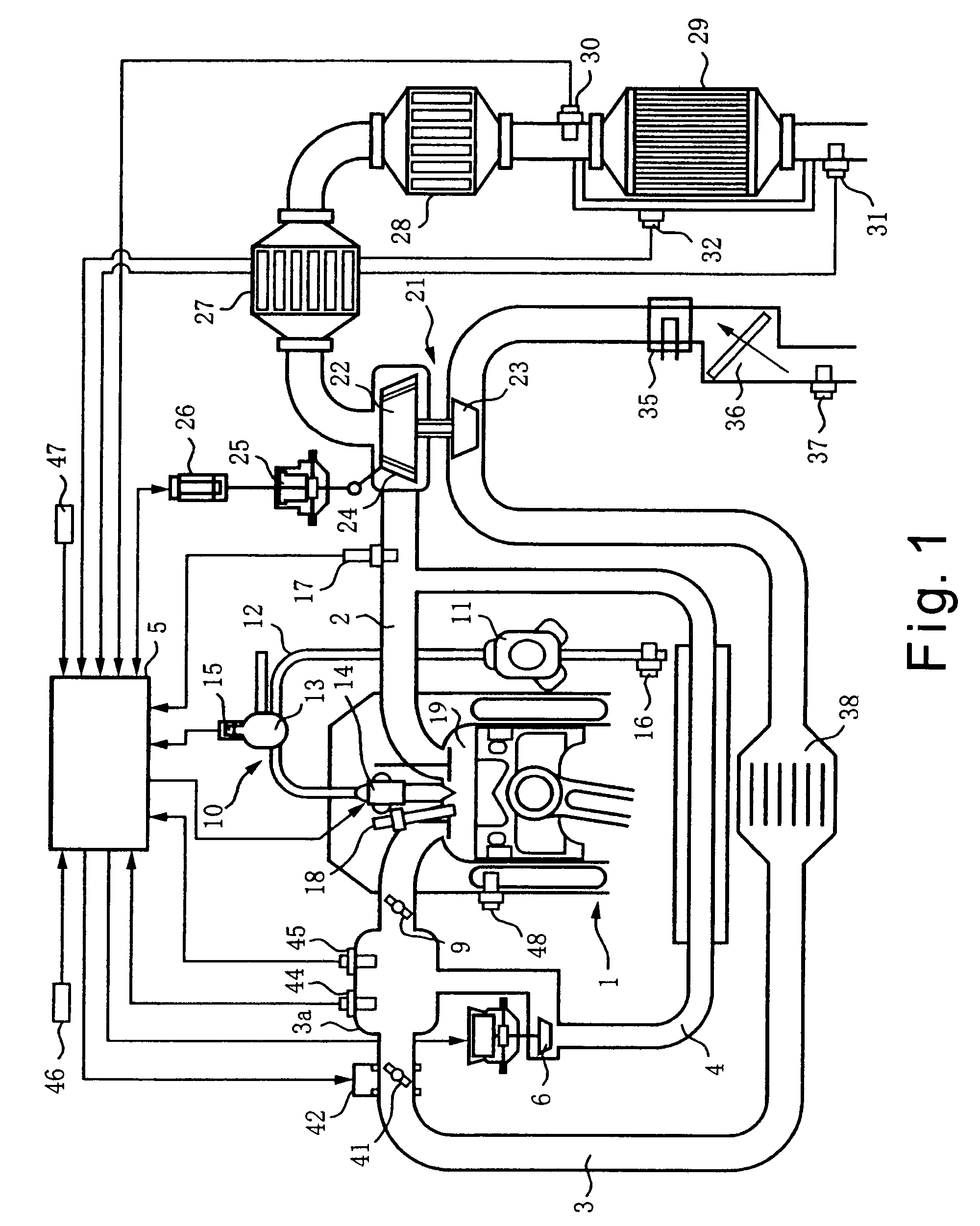
[0034]Referring initially to FIG. 1, a turbocharged engine control system is illustrated for an internal combustion engine such as a turbocharged diesel engine 1 in accordance with a first embodiment of the present invention. The turbocharged engine control system in accordance with the present invention can be applied to other internal combustion engines used in automobiles and the like. The engine 1 preferably performs a comparatively large quantity of exhaust gas recirculation (EGR).

[0035]As seen in FIG. 1, the engine 1 has an exhaust passage 2 and an intake passage 3 with a collector 3a. An EGR...


PUM


Abstract

A turbocharged engine control system is provided that comprises an exhaust gas after-treatment system and a variable-capacity turbocharger. The turbocharged engine control system is configured to estimate a clogging ratio of the exhaust gas after-treatment system based on an equivalent surface area of the exhaust gas after-treatment system. A correction value is determined based on a turbine outlet pressure and the correction value is added to the clogging ratio. A target nozzle opening value is corrected such that the nozzle opening value increases as the exhaust gas after-treatment system becomes more clogged. Consequently, as the exhaust gas after-treatment system becomes clogged, the increase in pressure on the inlet side of the exhaust turbine (which acts as back pressure with respect to the engine) is suppressed and the increase in the internal EGR ratio caused by residual gas is also suppressed.

Description

BACKGROUND OF THE INVENTION[0001]1. Field of the Invention[0002]The present invention generally relates to a turbocharged engine control system for an engine that is equipped with a variable-capacity turbo supercharger and has an exhaust gas after-treatment system in an exhaust passage such as a particulate filter. More specifically, the present invention relates to a turbocharged engine control system that prevents a rapid clogging in the exhaust gas after-treatment system caused by an increase in a pressure loss in the exhaust gas after-treatment system.[0003]2. Background Information[0004]Harmful exhaust components such as carbon particles and other particulate matters (particulate matter or “PM”) contained in an exhaust gas have become an enormous problem especially in diesel engines. Conventionally, various types of particulate matter capturing filters (Diesel Particulate Filter or “DPF”) have been used as exhaust gas after-treatment devices to collect and remove the particulat...

Claims


Application Information

Patent Timeline
Patent Type & Authority Patents(United States)
IPC IPC(8): F01N5/04F02B37/00F01N3/02F01N3/023F01N3/08F01N11/00F01N13/02F02B37/24F02D23/00F02D41/00F02D41/04F02D43/00F02M25/07
CPCF01N3/0814F01N13/009F01N3/0842F01N11/002F02B29/04F02B37/24F02D41/0007F02D41/1448F02M25/0707F02M25/0726F02M25/0754F02M25/0755F01N3/0821F01N2250/02F02B37/00F02D41/006F02D2200/0812F02M25/072Y02T10/146Y02T10/144Y02T10/47F02M26/05F02M26/17F02M26/22F02M26/46F02M26/47Y02T10/12Y02T10/40
Inventor SHIRAKAWA, TAKASHISAKAI, MAKOTO
Owner NISSAN MOTOR CO LTD
Why Eureka
Try Eureka