
Delayed locked loops and methods of driving the same

a technology of delayed locking loop and locked loop, which is applied in the direction of digital storage, pulse automatic control, instruments, etc., can solve the problems of high power consumption of the circuit, time delay (clock skew) by the internal circuit, and consumption of current, so as to reduce power consumption

Inactive Publication Date: 2006-05-16
SK HYNIX INC
View PDF4 Cites 31 Cited by
  • Summary
  • Abstract
  • Description
  • Claims
  • Application Information

AI Technical Summary

Benefits of technology

The patent describes a delay locked loop (DLL) and a method of driving it that can solve problems of excessive power consumption during the active power down mode. The method involves partially turning off the DLL while keeping its locking information during the active power down mode. This results in a reduction of power consumption while maintaining the desired performance. The disclosed DLL includes a clock buffer, delayed line, clock driver, phase detector, and shift register, which are all disabled during the active power down mode to save power. However, they are enabled during the precharge power down mode to ensure efficient performance.

Problems solved by technology

When the clock externally inputted is used internally, time delay (clock skew) by the internal circuit occurs.
In the DDR or DDRII SDRAM to which such a DLL is applied, however, the DLL is operated regardless of the power down mode which results in consumption of current.
Due to the continuous operation of the DLL, power consumption for the circuit is high.
Therefore, in the prior art, a lot of power is consumed since the DLL is always operated, even in the active power down mode.

Method used


Image

  • Delayed locked loops and methods of driving the same
  • Delayed locked loops and methods of driving the same
  • Delayed locked loops and methods of driving the same

Examples


Embodiment Construction

[0022]Hereinafter, a delay locked loop (DLL) and a method of driving the same will be described in detail with reference to the accompanying drawings.

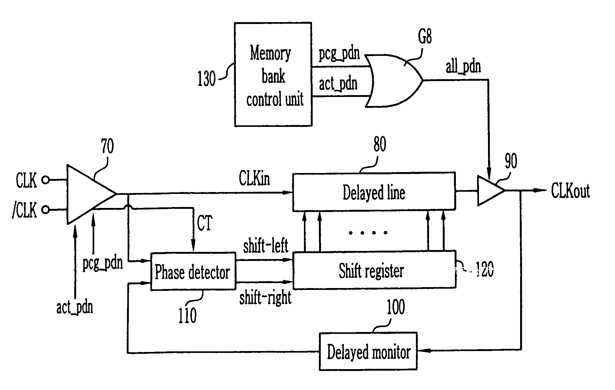
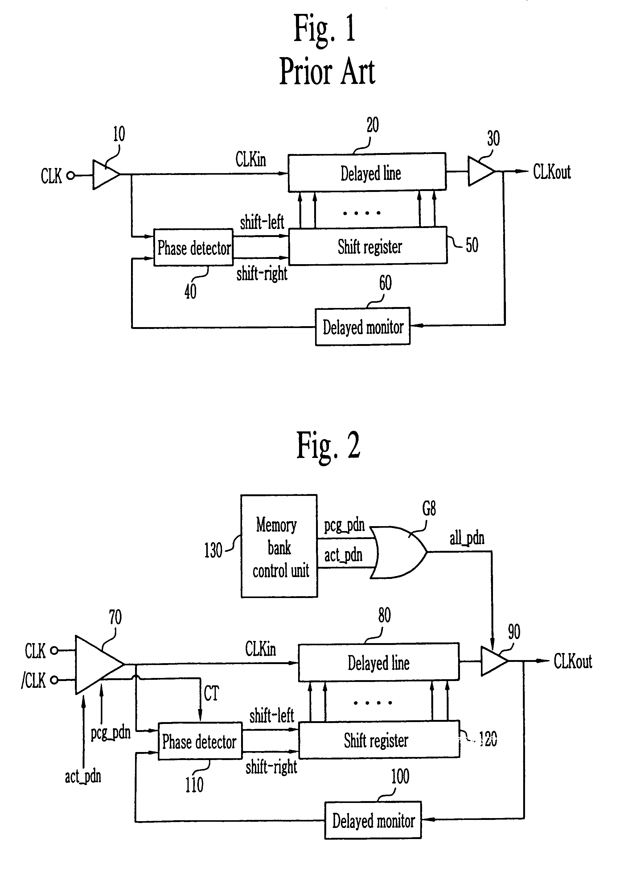
[0023]FIG. 2 is a block diagram illustrating the delay locked loop (DLL) according to one disclosed embodiment.

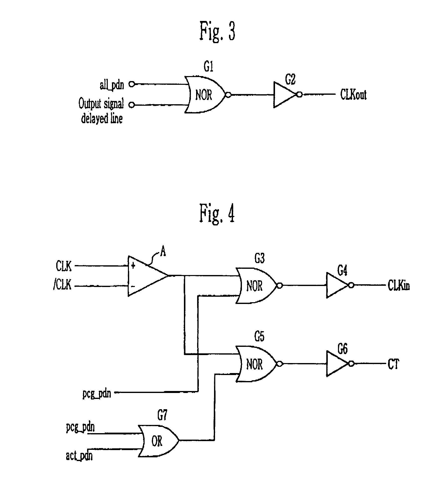
[0024]There is provided a clock buffer 70 for buffering external clocks CLK and / CLK to generate an internal clock CLKin and a control signal CT. The internal clock CLKin is delayed in a delayed line 80 for a certain time and is then inputted to a clock driver 90. The clock driver 90 buffers the internal clock CLKin delayed in the delayed line 80 to generate a clock signal CLKout.

[0025]Meanwhile, a memory bank control unit 130 outputs a precharge power down signal pcg_pdn and an active power down signal act_pdn. The precharge power down signal pcg-pdn is a signal that is enabled in the case where it enters the power down state in a state where a word line path within the bank in the synchronous DRAM such as the DDR SDRAM is shu...


PUM


Abstract

Disclosed are a delay locked loop (DLL) and a method of driving the same. The delay locked loop includes a clock buffer for buffering an inputted external clock to generate an internal clock, the clock buffer generating a control signal for disabling the internal clock depending on whether the power is down, a delayed line for delaying the internal clock, a clock driver for buffering the output of the delayed line to generate a clock signal, the clock driver disabling the clock signal depending on whether the power is down, a delay monitor for delaying the external clock, a phase detector for detecting the difference in a phase between the internal clock and the output of the delayed monitor to generate a detected signal, the phase detector being disabled according to the control signal, and a shift register for controlling the delayed line according to the detected signal from the phase detector. Therefore, it is possible to sufficiently satisfy power down excitation time while reducing current consumption of the entire semiconductor device during the power down state.

Description

CROSS REFERENCE TO RELATED APPLICATION[0001]This application is a continuation of U.S. patent application Ser. No. 10 / 654,498 filed Sep. 3, 2003, now U.S. Pat. No. 6,825,703 issued Nov. 30, 2004, which is hereby incorporated by reference.BACKGROUND OF THE DISCLOSURE[0002]A delay locked loop (DLL) and a method of driving the same are disclosed, which can reduce power consumption.[0003]In general, a clock in the system or the circuit is used as a reference for matching the operating timing. The clock is also used to secure much faster operation without error. When the clock externally inputted is used internally, time delay (clock skew) by the internal circuit occurs. In order to compensate for such time delay and thus make the internal clock have the same phase as the external clock, a delay locked loop (DLL) is used.[0004]Meanwhile, a DLL has the advantage that it is less sensitive to noise than the phase locked loop (PLL) that has been previously used. For this reason, DLLs has bee...

Claims


Application Information

Patent Timeline
Patent Type & Authority Patents(United States)
IPC IPC(8): H03L7/06H03L7/081G11C5/00G11C11/407G11C11/4076H03L7/08H03L7/089
CPCH03L7/0802H03L7/089H03L7/0814H03L7/0816G11C11/407
Inventor KWAK, JONG TAE
Owner SK HYNIX INC
Learn More