Fiber-optic based cavity ring-down spectroscopy apparatus

Inactive Publication Date: 2006-05-16
THE TRUSTEES FOR PRINCETON UNIV
View PDF32 Cites 21 Cited by
  • Summary
  • Abstract
  • Description
  • Claims
  • Application Information

AI Technical Summary

Benefits of technology

[0030]According to yet another aspect of the invention, the apparatus further comprises a sensor formed from a cylindrical body and wrapped with a section of the expose

Problems solved by technology

Gases such as N2, O2, H2, Ar, and He are used to manufacture integrated circuits, for example, and the presence in those gases of impurities—even at parts per billion (ppb) levels—is damaging and reduces the yield of operational circuits.
Further, the presence of impurities, either inherent or deliberately place, in liquids have become of particular concern of late.
These methods have several features, discussed in U.S. Pat. No. 5,528,040 issued to Lehmann, which make them difficult to use and impractical for industrial applications.
At present, CRDS is limited to spectroscopic regions where high reflectivity dielectric mirrors can be used.
This has significantly limited the usefulness of the method in much of the ultraviolet and infrared regions, because mirrors with suffi

Method used


Image

  • Fiber-optic based cavity ring-down spectroscopy apparatus
  • Fiber-optic based cavity ring-down spectroscopy apparatus
  • Fiber-optic based cavity ring-down spectroscopy apparatus

Examples


Embodiment Construction

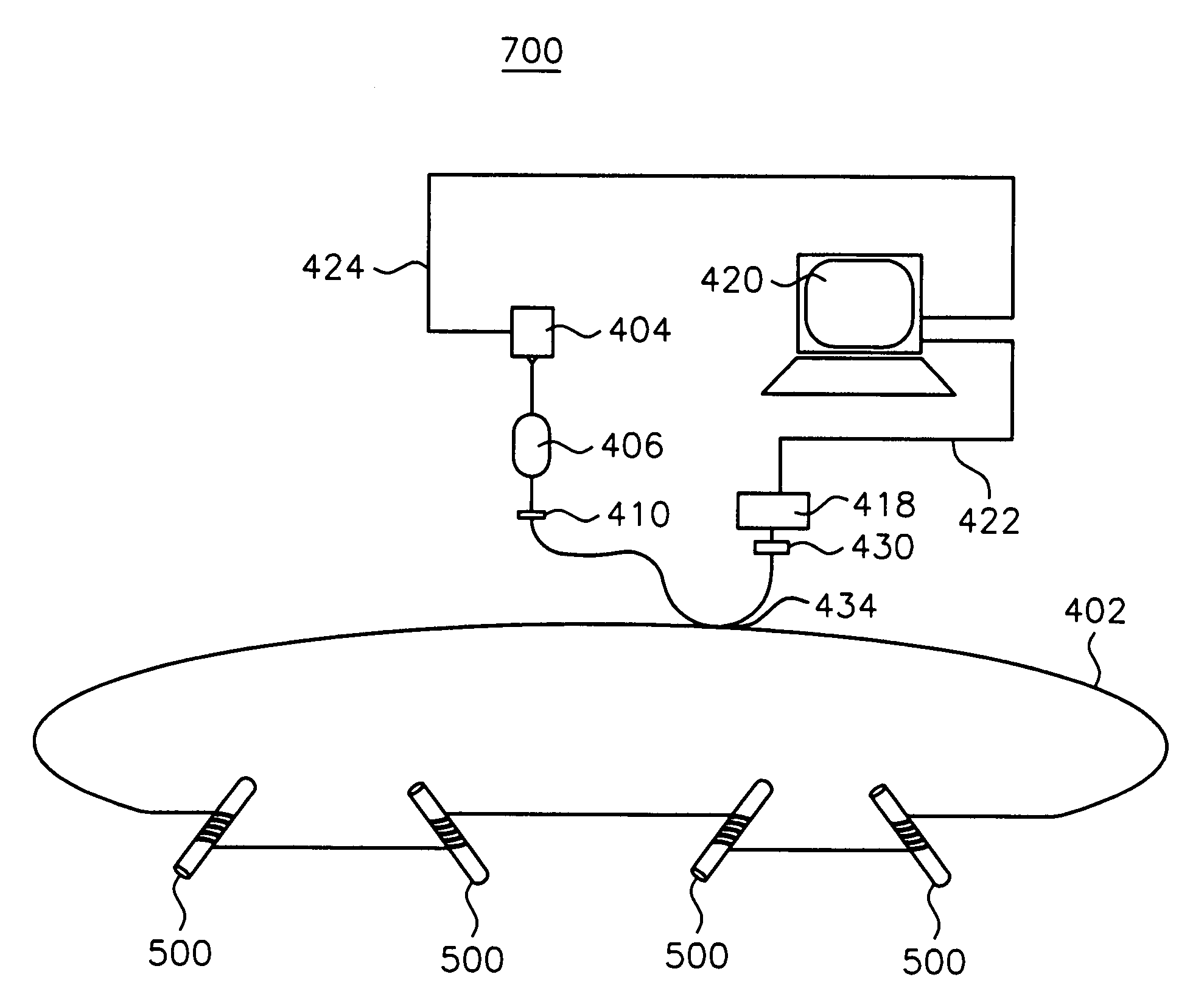
[0045]FIG. 4 illustrates fiber optic based ring-down apparatus 400 according to a first exemplary embodiment of the present invention through which trace species, or analytes, in gases and liquids may be detected. In FIG. 4, apparatus 400 includes resonant fiber optic ring 408 which has fiber optic cable 402 and sensors 500 (described below in detail) distributed along the length of fiber optic cable 402. The length of resonant fiber optic ring 408 is easily adaptable to a variety of acquisition situations, such as perimeter sensing or passing through various sections of a physical plant, for example. Although as shown, sensors 500 are distributed along the length of fiber optic loop 408, the invention may be practiced using only one sensor 500, if desired. The distribution of more than one sensor 500 allows for sampling of a trace species at various points throughout the installation site. The invention may also be practiced using a combination of sensors 500 with straight section ...


PUM


Abstract

An apparatus for detection and measurement of trace species in a gas or liquid sample. A ring down cell formed from a fiber optic ring is exposed to the sample gas or liquid. A coherent source emits radiation into the fiber optic ring, which in turn is received at an output thereof. The fiber optic ring has a portion thereof, between the input and output, exposed to the sample gas or sample liquid. A processor is coupled to the receiver and determines the level of trace species in the gas or liquid sample based on the rate of decay of the radiation within the fiber optic ring.

Description

FIELD OF THE INVENTION[0001]This invention relates generally to absorption spectroscopy and, in particular, is directed to the use of a fiber-optic resonator for ring-down cavity spectroscopy.BACKGROUND OF THE INVENTION[0002]Referring now to the drawing, wherein like reference numerals refer to like elements throughout, FIG. 1 illustrates the electromagnetic spectrum on a logarithmic scale. The science of spectroscopy studies spectra. In contrast with sciences concerned with other parts of the spectrum, optics particularly involves visible and near-visible light—a very narrow part of the available spectrum which extends in wavelength from about 1 mm to about 1 nm. Near visible light includes colors redder than red (infrared) and colors more violet than violet (ultraviolet). The range extends just far enough to either side of visibility that the light can still be handled by most lenses and mirrors made of the usual materials. The wavelength dependence of optical properties of materi...

Claims


Application Information

Patent Timeline
IPC IPC(8): G01N21/00G01J3/42G01N21/27G01N21/39G01N21/55G01N21/77
CPCG01J3/42G01N21/39G01N21/552G01N2021/7789G01N2021/391
Inventor LEHMANN, KEVIN K.TARSA, PETER B.RABINOWITZ, PAUL
Owner THE TRUSTEES FOR PRINCETON UNIV
Why Eureka
Try Eureka