Eureka AIR delivers breakthrough ideas for toughest innovation challenges, trusted by R&D personnel around the world.

Light amplifier and light amplifying method

a technology of light amplifier and light amplifier, which is applied in the direction of electromagnetic transmission, optical transmission, electromagnetic repeaters, etc., can solve the problems of difficult to reduce the nf below 3 db, and difficult to effectively reduce the loss of transmission path fiber

Active Publication Date: 2006-05-16
FUJITSU LTD
View PDF5 Cites 7 Cited by
  • Summary
  • Abstract
  • Description
  • Claims
  • Application Information

AI Technical Summary

Benefits of technology

[0020]The level of the light outputted from the second discrete light amplifier may be set so that a first upper limit value set based on the amount of waveform deterioration caused by the nonlinear optical effect due to the output side optical fiber is not exceeded.
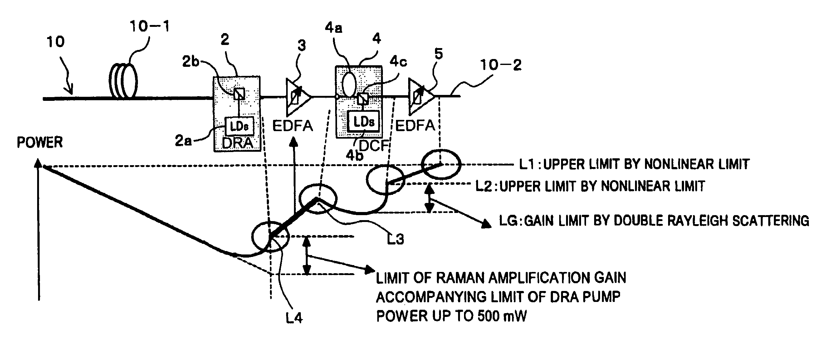
[0035]As described above, the light amplifier of the present invention includes the Raman excitation section connected to the input side optical fiber and backwardly Raman-exciting the input side optical fiber, the first discrete light amplifier capable of carrying out a discrete amplification of the light from the input side optical fiber and Raman-amplified by the exiting light from the Raman excitation section, the dispersion compensating fiber Raman amplifier capable of, while dispersion-compensating the light amplified by the first discrete light amplifier in the dispersion compensating fiber, Raman-amplifying the light propagating in the dispersion compensating fiber, and the second discrete light amplifier capable of carrying out a discrete amplification of the light from the dispersion compensating fiber Raman amplifier, therefore, there is an advantage that the gain and the noise characteristic can be obtained, which are required for the direct light amplification repeater in order to keep up with the trend toward higher transmission speeds.

Problems solved by technology

In the technique described in Patent document 1 mentioned above, a Raman amplification is not carried out for the input side transmission path fiber, therefore, it is difficult to make the loss of the transmission path fiber appear effectively low and it is also difficult to reduce the NF below 3 dB, which is a theoretical limit that can be realized in an erbium doped optical fiber amplifier (EDFA) (refer to FIG. 5(b) shown in Patent document 1).
Moreover, the techniques described in Patent documents 2 and 3 mentioned above also are not for disclosing a technique that realizes the gain and the noise characteristic of a light amplification repeater in accordance with the trend toward higher transmission speeds as described above.

Method used


Image

  • Light amplifier and light amplifying method
  • Light amplifier and light amplifying method
  • Light amplifier and light amplifying method

Examples


Embodiment Construction

[0039]The embodiments of the present invention are explained below with reference to drawings.

[0040]In addition to the above-mentioned objects of the present invention, other technical problems and means to solve the technical problems and its operational effect will be cleared in the description of the embodiments disclosed below.

[A] Description of an Embodiment of the Present Invention

[0041][A1] Configuration

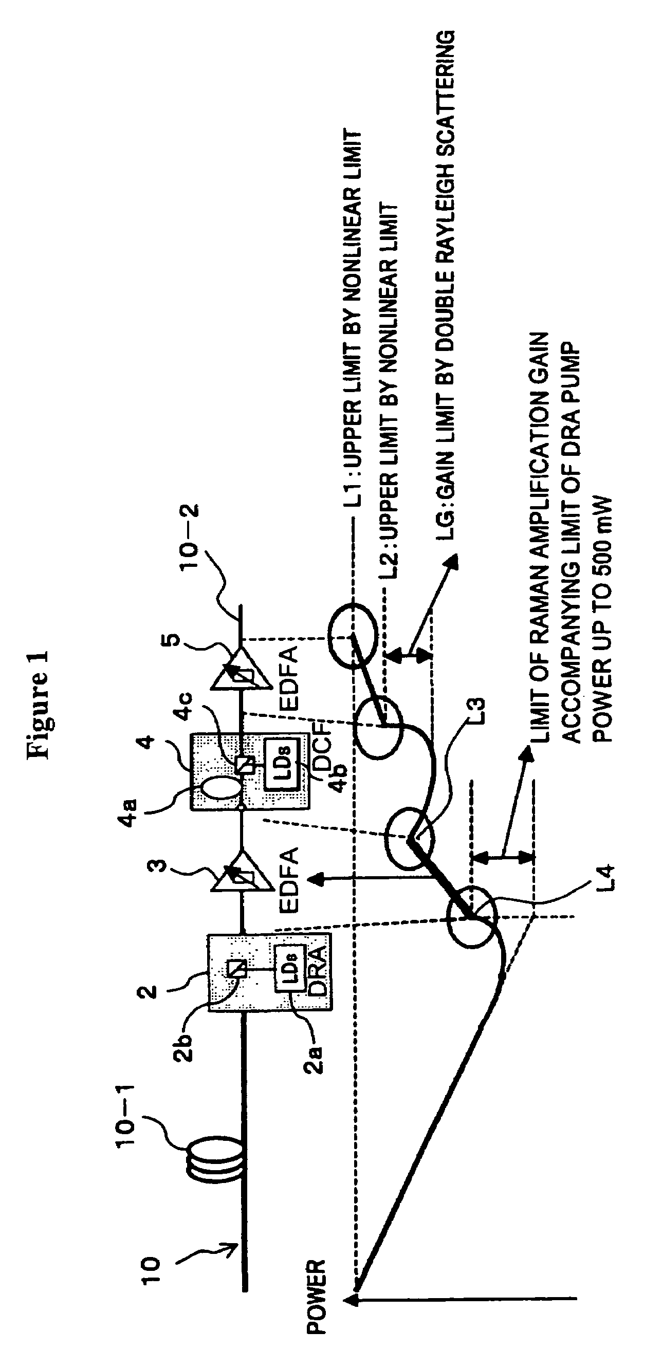
[0042]FIG. 1 is a diagram showing a light amplifier according to an embodiment of the present invention. A light amplifier 1 shown in FIG. 1 is applied as, for example, a repeater node interposed on an optical transmission path 10 and carries out a direct light amplification repeater of a light signal propagating in the optical transmission path 10. In other words, the light amplifier 1 as a repeater node carries out the direct light amplification of a light signal inputted from an input side optical fiber 10-1 constituting the optical transmission path 10 and sends out the li...


PUM


Abstract

The present invention relates to a light amplifier capable of obtaining the gain and the noise characteristic required for a direct light amplification repeater in order to keep up with the trend toward higher transmission speeds. The light amplifier includes a Raman excitation section for backwardly Raman-exciting an input side optical fiber, a first discrete light amplifier capable of carrying out a discrete amplification of light from the input side optical fiber and Raman-amplified by exiting light from the Raman excitation section, a dispersion compensating fiber Raman amplifier capable of, while dispersion-compensating the light amplified by the first discrete light amplifier in a dispersion compensating fiber, Raman-amplifying the light propagating in the dispersion compensating fiber, and a second discrete light amplifier capable of carrying out a discrete amplification of the light from the dispersion compensating fiber Raman amplifier.

Description

BACKGROUND OF THE INVENTION[0001]1) Field of the Invention[0002]The present invention relates to a light amplifier and a light amplifying method suitable for use in an optical communication system and, more particularly, to a light amplifier and a light amplifying method suitable for use in a wavelength division multiplexing (WDM) optical communication system and, still more particularly, to a light amplifier and a light amplifying method suitable for use in carrying out a repeater amplification in a wavelength division multiplexing optical communication system.[0003]2) Description of the Related Art[0004]In recent years, a construction of a photonic network using the wavelength division multiplexing transmission technique is in progress for practical use. In the photonic network, by lengthening the distance across which a light signal to be repeated can transmit by being directly amplified without being converted into an electric signal, the cost of the whole optical network is red...

Claims


Application Information

Patent Timeline
Patent Type & Authority Patents(United States)
IPC IPC(8): H01S3/00H04B10/07H04B10/2507H04B10/2525H04B10/2543H04B10/29H04B10/294
CPCH01S3/06758H04B10/291H04B10/2916H01S3/06725H01S3/1608H04B2210/256H01S3/302
Inventor SUGAYA, YASUSHIONAKA, MIKI
Owner FUJITSU LTD
Why Eureka
Eureka Blog
Learn More