DC/AC converter to convert direct electric voltage into alternating voltage or into alternating current

a technology of alternating voltage and converter, which is applied in the direction of ac-dc conversion, single network parallel feeding arrangement, electric variable regulation, etc., can solve the problems of poor emc behavior on the input side, lack of four-quadrant operation (reactive power capacity), or the entire or at least a large part of power transferred to the output, etc., to avoid drawbacks, better electromagnetic compatibility, and better efficiency

Active Publication Date: 2006-05-16
FRAUNHOFER GESELLSCHAFT ZUR FOERDERUNG DER ANGEWANDTEN FORSCHUNG EV
View PDF5 Cites 68 Cited by
  • Summary
  • Abstract
  • Description
  • Claims
  • Application Information

AI Technical Summary

Benefits of technology

[0034]Based on the previously described state of the art, the present invention provides a DC / AC converter which combines the advantages of the aforedescribed symmetrical and unsymmetrical timing including the advantages of single-phase chopping while at the same time avoiding the drawbacks associated with the aforementioned prior art. In particular, a DC / AC converter in accordance with the invention has better efficiency and better electromagnetic compatibility than hitherto prior-art DC / AC converters while at the same time avoiding the use of complicated and expensive circuit topologies. Moreover, the object is to make possible using the DC / AC converter selectively in grid feeding operation as well as in island operation.
[0035]A key element of the present invention is that a DC / AC converter having two DC voltage connections, between which are provided in a parallel circuit configuration, an intermediate energy storage and a bridge circuit, which has at least two parallel branches each provided with two switch units connected in series to each of which a rectifier diode is connected in parallel, and having at least two AC voltage connections, of which each is connected via connecting lines, in each of which an inductor is provided, to one of the parallel branches of the bridge circuit respectively between two switch units via a connecting node, is improved in that between the at least two connecting lines, two electric connecting paths are provided, in each of which a switch and a rectifier diode connected in series are provided, and in that the rectifier diodes in the individual connecting paths are switched to each other in opposite conducting direction.
[0039]With the invention providing the additional connecting paths between the connecting lines to tap the bridge voltage opens the possibility of alternative recovery paths along which the inductor current can circulate due to the demagnification processes of the inductors.
[0040]The efficiency of the DC / AC converter is considerably improved by this means, because no energy losses connected with energy backflow into the buffer capacitor can occur. At the same time, in a recovery case, unlike in the prior art (symmetrical timing), the sum of the solar generator voltage and the present grid voltage is not fed to the inductor but solely the momentary grid voltage, which permits considerably reducing the disadvantageous current ripples in the inductors and in the output current described in the prior art.
[0041]Finally, the additional recovery paths provided according to the present invention permit complete ohmic decoupling between the DC voltage connections and the connected DC voltage source, preferably a solar generator, and the AC voltage connections during the recovery phase. This has the advantageous consequence that high-frequency voltage leaps at the connection lines of the solar generator as occur in the prior art (unsymmetrical timing respectively single-phase chopping) can be fundamentally avoided. In this manner, the hazard potential mentioned in the introduction and the discussed problem regarding electromagnetic compatibility in operating such a type DC / AC converter are reduced to such an extent that it may be considered safe.

Problems solved by technology

A disadvantage, however, is poor EMC behavior on the input side as well as sometimes lacking four-quadrant operation (reactive power capacity) depending on the type of timing applied.
An essential drawback in all the just mentioned topologies, however, is that either the entire or at least a large part of the power transferred to the output has to be intermediately stored in an inductor or transferred to the output via coupling capacitors.
In all these circuits, this results in distinctly lower efficiency values in comparison to a simple bridge circuit.
Furthermore, these circuits are sometimes very complex and difficult to control.
This voltage leads to neither safety problems nor problems with regard to electromagnetic compatibility.
However, two drawbacks are inevitably connected with the symmetrical mode of operating the DC / AC converter.
Furthermore, considerable switch losses occur during the periodic switching of the switches A,D due to the not ideal dynamic properties of the recovery diodes DB and DC, correspondingly also during the negative half wave.
Due to the high voltage, the inductors L1 and L2 are rapidly demagnified, which leads to high current fluctuations, a so-called current ripple, in the output current, which ultimately leads to marked losses in the inductor and to EMC problems.
However, one drawback, which is shown in FIGS. 4a to 4d, is inevitably connected with unsymmetrical timing.
However, these potential fluctuations occur as high-frequency voltage leaps with frequencies of up to more than 100 kHz and lead to extremely large leakage currents via parasitic capacities, as usually occur in large-area solar generators, which decisively diminish the electromagnetic compatibility of such systems.
Moreover, the high-frequency leaps in voltage represent a considerable potential hazard when coming into contact with the insulated module surfaces due to capacitive coupling.

Method used


Image

  • DC/AC converter to convert direct electric voltage into alternating voltage or into alternating current
  • DC/AC converter to convert direct electric voltage into alternating voltage or into alternating current
  • DC/AC converter to convert direct electric voltage into alternating voltage or into alternating current

Examples


Embodiment Construction

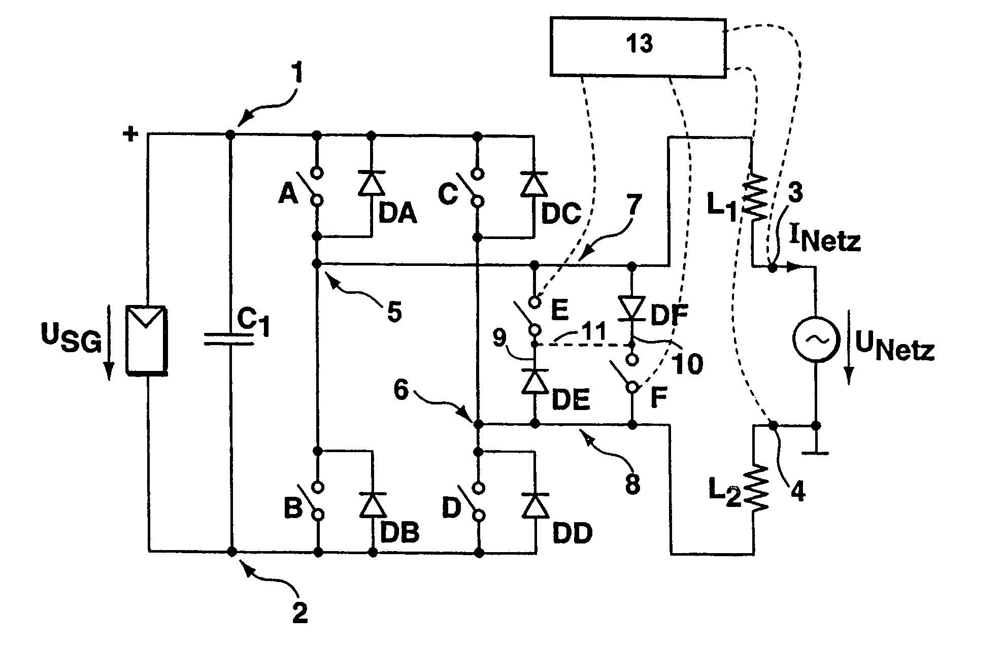
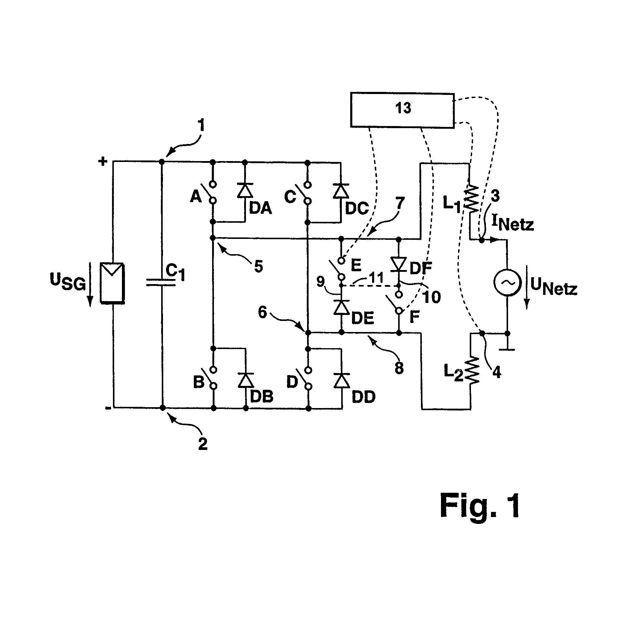
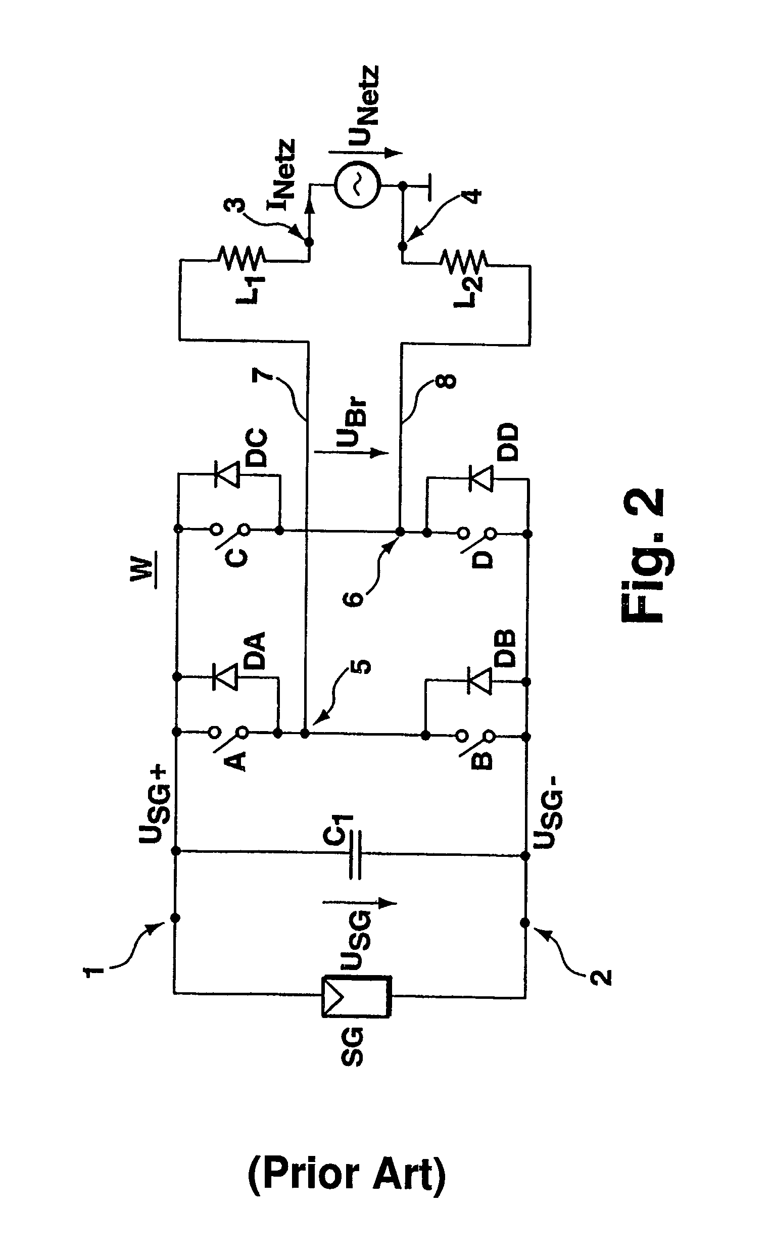
[0054]As in the DC / AC converter circuit set up described as the closest prior art with reference to FIG. 2, the DC / AC converter according to FIG. 1 is also provided with a parallel circuit comprising an energy intermediate storage C1, preferably in the form of a buffer capacitor, and a bridge circuit. The parallel circuit is connected between the DC voltage connection 1,2. As in the bridge circuit shown in FIG. 2, the bridge circuit is provided with four switch units A, B, C, D to which the rectifier diodes DA, DB, DC, DD are connected in parallel respectively. The difference relative to the prior-art topology according to FIG. 2 is the provision of two additional electric connecting paths 9, 10 between the connecting lines 7, 8 to tap the bridge voltage UBr at the connecting nodes 5,6. Located in each individual connecting paths 9, 10 is a switch E, F and a rectifier diode DE, DF respectively, which are switched relative to each other in an opposite conducting direction. All the ot...


PUM


Abstract

A DC / AC converter is disclosed having two DC voltage connections (1,2), between which are provided in a parallel circuit configuration, an intermediate energy storage (C1) and a bridge circuit providing at least two parallel branches, each branch providing two in-series-connected switch units (A,B and C,D), to each of which a rectifier diode (DA,DB,DC DD) is connected in parallel, and having at least two AC connections, of which each single AC connection is connected via a connecting line, in each of which an inductor (L1 respectively L2) is provided, to one of the parallel branches of the bridge circuit between two the switch units (A,B respectively C,D) via one connecting node. In at least two connecting lines, two separate electrical connecting paths are provided, in each of which a switch (E respectively F) and an in-series-switched rectifier diode (DE respectively DF) are provided. The rectifier diodes (DE,DF) in the single connecting paths are switched in an opposite conducting direction.

Description

BACKGROUND OF THE INVENTION[0001]1. Field of the Invention[0002]The present invention relates to a DC / AC converter to convert direct electric voltage (DC) into alternating current or into alternating voltage (AC). Such type converters are used, for example, to supply energy to the public electricity grid or to build an independent island grid where only DC voltage energy sources are available, such as for example photovoltaic systems, fuel cells, batteries, etc.[0003]2. Description of the Prior Art[0004]The purpose of a DC / AC converter for supplying energy to an existent AC voltage grid is to generate an alternating current which is to be adapted with regard to phase position and amplitude of the potential curve of the AC voltage, preferably to a 50 or 60 Hz sine-shaped grid voltage. The purpose of a DC / AC converter for supplying energy to an independent island grid, on the other hand, is to generate an AC voltage that is stable in voltage and frequency. In order to operate any desi...

Claims


Application Information

Patent Timeline
Patent Type & Authority Patents(United States)
IPC IPC(8): H02M7/5387H02J3/38H02M3/24H02M7/48
CPCH02M7/48H02M7/5387Y02E10/563H02J3/383H02J2300/24H02J3/381Y02E10/56H02J3/40
Inventor SCHMIDT, HERIBERTSIEDLE, CHRISTOPHKETTERER, JURGEN
Owner FRAUNHOFER GESELLSCHAFT ZUR FOERDERUNG DER ANGEWANDTEN FORSCHUNG EV
Why Eureka
Try Eureka