Internal combustion engine combination with direct camshaft driven coolant pump

Inactive Publication Date: 2006-05-23
LITENS AUTOMOTIVE INC
View PDF25 Cites 12 Cited by
  • Summary
  • Abstract
  • Description
  • Claims
  • Application Information

AI Technical Summary

Benefits of technology

[0014]The objective may also be achieved by providing the combination comprising a valve controlled piston and cylinder internal combustion engine having a piston driven output shaft and a valve actuating camshaft driven by the output shaft and a coolant system including a coolant flow path which passes through the engine in cylinder cooling relation and thereafter through a cooling zone. The coolant system includes a coolant pump comprising a pump housing within the flow path including an inlet opening configured and positioned to receive coolant from the flow path and an outlet opening configured and positioned to discharge coolant into the flow path. An impeller rotating structure is mounted directly to the camshaft so as to be rotatably driven thereby about an axis concentric to a rotational axis of the camshaft. A pump impeller is operatively mounted to the impeller rotating structure within the pump housing. The pump impeller is constructed and arranged to draw the coolant into the pump housing through the inlet opening and discharge the coolant at a higher pressure through the outlet opening during rotation thereof. A damper assembly is disposed within the pump housing and is rotatable to dampen

Problems solved by technology

With the abundance of accessories, there is limited space in the front of the engine.
However, the camshaft is subjected to torsional vibrations due to, for example, the natural operating frequency of the engine, cyclic resistance to camshaft rotation, and vibrations occurring in the camshaft drive chain/belt.
Such torsional vibrations can cause excessive wear in the chain/belt and at the cam surfaces.
As a result, it is known to provide vibration damping means for the camshaft so torsional vibrations may be damped.
Camshaft

Method used


Image

  • Internal combustion engine combination with direct camshaft driven coolant pump
  • Internal combustion engine combination with direct camshaft driven coolant pump
  • Internal combustion engine combination with direct camshaft driven coolant pump

Examples


Embodiment Construction

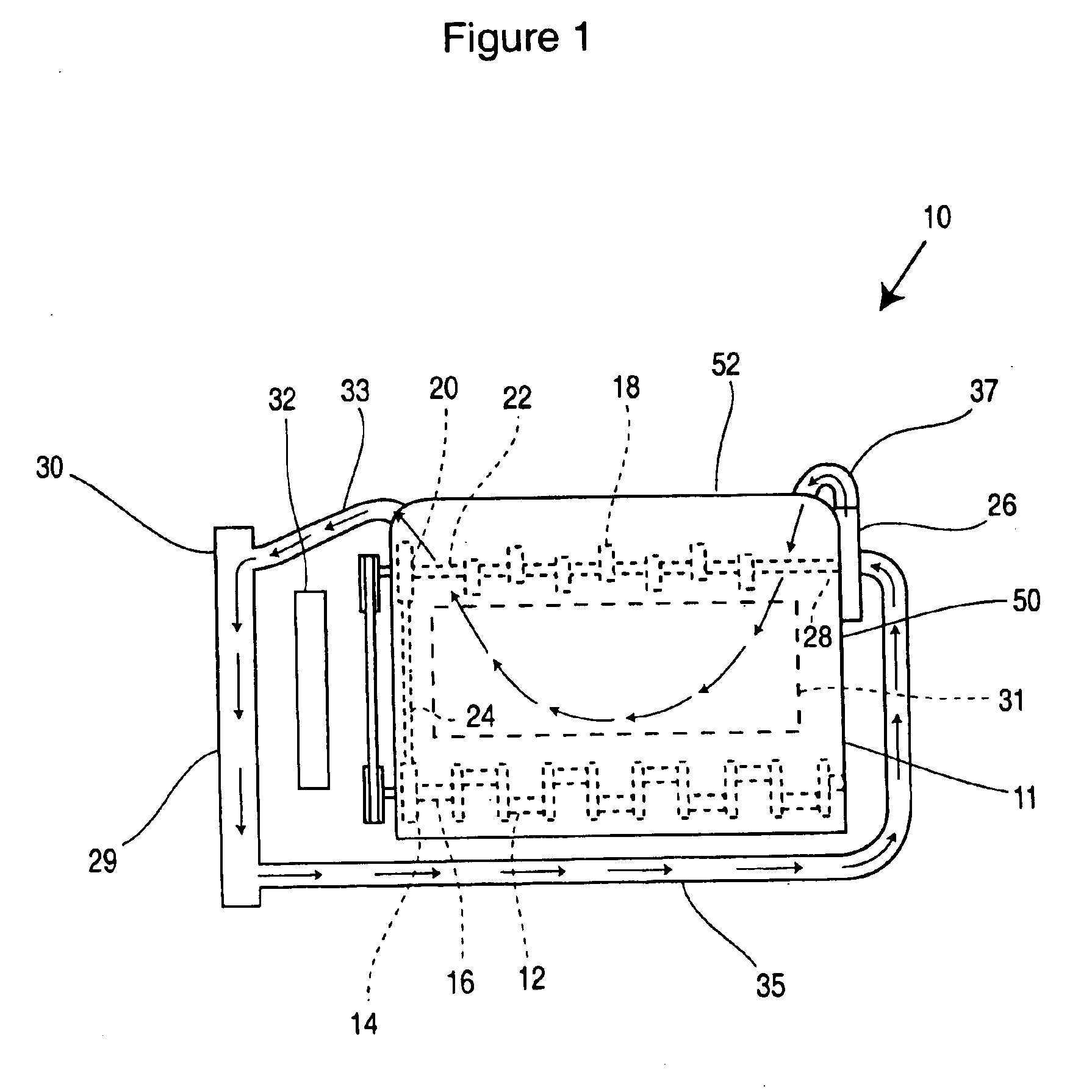
[0040]FIG. 1 is a schematic view illustrating a valve controlled piston and cylinder internal combustion engine 10 for an automobile. As is conventional, the engine 10 includes a piston driven output shaft 12, or crankshaft, having a driving sprocket or pulley 14 fixedly mounted thereto at one end 16 thereof. A valve actuating camshaft 18, which operates the valve mechanisms of the engine 10, has a driven sprocket or pulley 20 mounted thereto at one end 22 thereof. An endless chain or belt 24 is trained about the driving sprocket / pulley 14 of the crankshaft 12 and the driven sprocket / pulley 20 of the camshaft 18. The driven sprocket / pulley 20 receives driving force from the driving sprocket / pulley 14 via the chain / belt 24, which transmits such force to the camshaft 18. Thus, the camshaft 18 is coupled to the crankshaft 12 of the engine 10 so as to be driven by the crankshaft 12 and rotate under power from the engine 10. It should be understood that the internal combustion engine 10 ...


PUM


Abstract

A coolant pump for use with an internal combustion engine having a crankshaft and a camshaft driven by the crankshaft includes a pump housing fixedly mountable to the engine. The pump housing includes an inlet opening to receive coolant and an outlet opening to discharge coolant. An impeller shaft is operatively coupled to the camshaft so as to be rotatably driven thereby. A pump impeller is operatively mounted to the impeller shaft within the pump housing, the pump impeller rotatable to draw the coolant into the pump housing through the inlet opening and discharge the coolant at a higher pressure through the outlet opening. The pump impeller includes first and second shrouds separated by a plurality of vanes. The first and second shrouds and plurality of vanes are configured and positioned such that a resultant thrust load acting on the pump impeller and hence the impeller shaft is approximately zero.

Description

[0001]The present application is a Continuation-in-Part of U.S. application Ser. No. 10 / 075,995, filed Feb. 15, 2002, now U.S Pat. No. 6,588,381, and also claims priority to U.S. Provisional Application No. 60 / 268,599, filed Feb. 15, 2001, the entireties of both being hereby incorporated into the present application by reference.FIELD OF THE INVENTION[0002]The present invention relates to a coolant pump for use with an internal combustion engine. More particularly, the present invention relates to a coolant pump that is mounted directly to the camshaft of the internal combustion engine.BACKGROUND OF THE INVENTION[0003]Conventional coolant pumps, also referred to as water pumps, are typically mounted on the front of the engine frame so that the pump can be operated by a belt drive system. Specifically, the output shaft, or crankshaft, of the engine includes a driving pulley fixed thereto forming part of the drive system. The drive system includes an endless belt that is trained about...

Claims


Application Information

Patent Timeline
IPC IPC(8): F01P5/10F01L1/02F01L1/047F01L1/053F01L1/46F01P5/12F02B63/06F04D13/02
CPCF01L1/02F01L1/024F01L1/047F01L1/053F01P5/12F02B63/06F04D13/02F04D29/106F01L1/46F05B2260/603F05D2260/6022
Inventor KOMOROWSKI, JACEK S.
Owner LITENS AUTOMOTIVE INC
Why Eureka
Try Eureka