Boring head with tool advance independent of rotation

a technology of rotating and rotating heads, which is applied in the direction of driving apparatus, milling equipment, and large fixed members, etc., can solve the problems of cutting effort, seat hardness increase, boring head type abandoned, etc., and achieve the effect of constant surface finish

Inactive Publication Date: 2006-05-23
MASHIIN SERUDEI
View PDF18 Cites 3 Cited by
  • Summary
  • Abstract
  • Description
  • Claims
  • Application Information

AI Technical Summary

Benefits of technology

[0009]It is the purpose of the present invention to provide a boring head with cutting advance independent of the rotation which overcomes these drawbacks and makes it possible, among other things, to obtain a constant surface finish over the entirety of the machined part, whatever the angle of slope between 0 and 90°.
[0019]The interpolated combination of this tool-displacement function onto an axis U, corresponding to the radius of machining with the spindle-displacement function, along an approximately vertical axis Z, makes it possible to machine any surface of revolution about the longitudinal axis of the head and therefore about the axis of the pilot, if this head is secured to a pilot rod.
[0021]This motor is therefore equipped with means making it possible, at any moment, to determine the speed and angular position of its rotor and for the control unit to adjust it to suit requirements. That allows the tool to be positioned perfectly by imparting a programmed variable speed to it, and therefore makes it possible to work with constant chips, that is to say under the best possible cutting conditions, whatever the angle formed by the machined surface with respect to the longitudinal axis of the spindle.

Problems solved by technology

This type of boring head has been abandoned because of the lack of cutting effort provided manually which did not allow seats of increasing hardness to be machined.
Such a head can machine seats of greater hardness because the tool has greater torque, but does have the same disadvantages as the manual head, namely the fact that it is impossible to control the surface finish, at least on some of the conical surfaces that make up a seat.
Specifically, and in particular, on conical surfaces with a steep slope, the tool has to move radially at a higher speed which means that the punctual cutting edge of the tool does not have time to pass again over the machined surface, and this leads to a somewhat unsatisfactory surface finish.
Likewise, it is known that heads in which the cutting radius is altered in proportion to the number of revolutions of the spindle cannot produce a cylindrical bore even though such an ability would make acquiring them a more viable option.

Method used


Image

  • Boring head with tool advance independent of rotation
  • Boring head with tool advance independent of rotation
  • Boring head with tool advance independent of rotation

Examples


Embodiment Construction

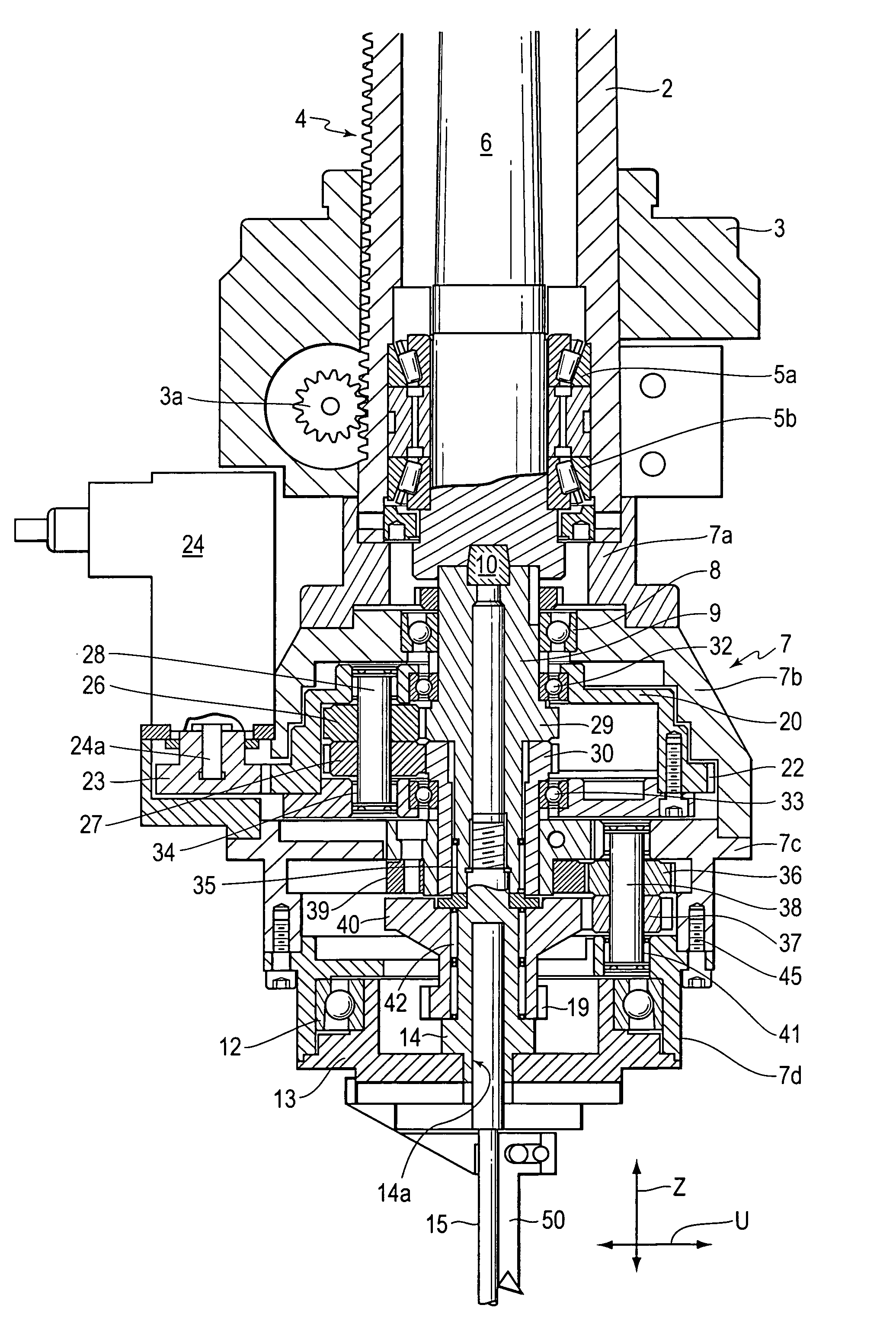
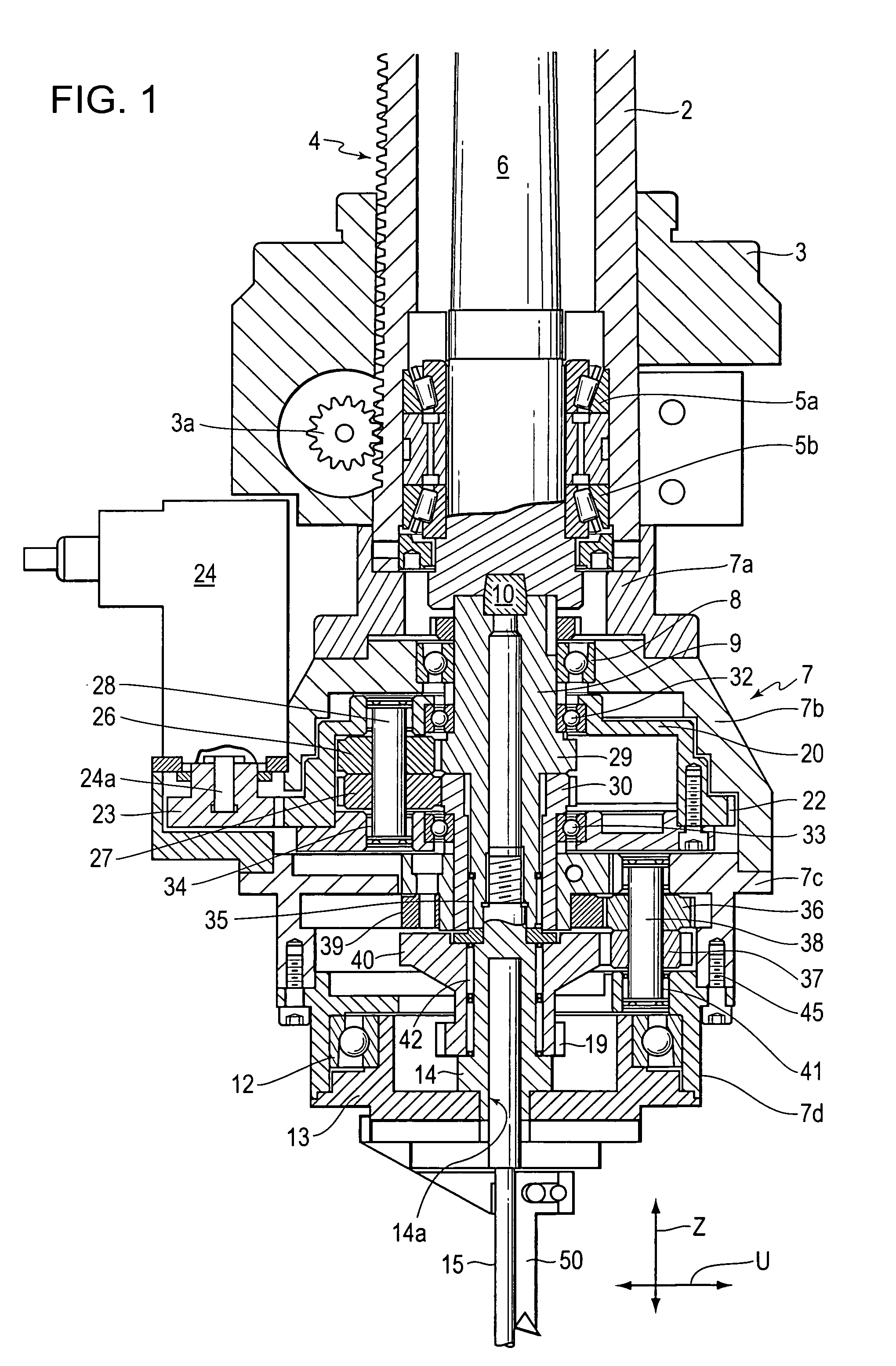
[0026]In FIG. 1, the numerical reference 2 denotes the quill of a machine tool and, in particular, of a machine for grinding valves. This quill is mounted so that it can slide in a structure 3 that allows it to be moved in a horizontal plane with respect to the structure of the machine. It may itself be moved vertically by the collaboration of a gear wheel 3a with the rack 4 with which it is equipped. The gear wheel 3a is connected in terms of rotation to a manual command, not depicted, and to an electric motor 21 (FIG. 3). This quill contains tapered roller bearings 5a, 5b which guide the rotation of a spindle 6 connected to an electric motor 11.

[0027]The head according to the invention is made up of the body 7 in several parts, of which the upper part 7a, in the form of a sleeve, is fixed to the lower end of the quill 2. A bell-shaped part 7b of the body 7 contains a roller bearing 8 guided in terms of rotation to an intermediate axial shaft 9 which is connected in terms of rotati...


PUM

PropertyMeasurementUnit
angleaaaaaaaaaa
angleaaaaaaaaaa
rotational speedaaaaaaaaaa

Abstract

The transmission of the rotational movement to the driving pinion of the carriage is provided by:a first gear train with a cage mounted so that it can rotate about the axial shaft and the crown wheel of which meshes with a pinion fitted onto the shaft of an electric motor carried by the body, this train carrying at least two superposed planet pinions and meshing, in the case of the upper one, with a set of teeth formed around the axial shaft and, in the case of the lower one, with an output sun gear,a second train, the sun gear of which is secured to the output sun gear of the first train and meshes with the upper planet pinion of at least one set of superposed planet pinions which are mounted so that they are free to rotate in a continuation of the body, the lower planet pinion meshing with a set of teeth which, formed on the driving pinion of the carriage, is distinct from the set of teeth that collaborates with the rack of this carriage,these two sun gears having ratios which are other than 1 and inverse, while the electric motor driving the cage and the one translating the quill are powered under the control of the command and control unit.

Description

[0001]This is a Continuation of application Ser. No. 10 / 237,098 filed Sep. 9, 2002, which claims the benefit of U.S. Provisional Application No. 60 / 352,267 filed Jan. 30, 2003. The entire disclosure of the prior applications is hereby incorporated by reference herein in its entirety.BACKGROUND OF THE INVENTION[0002]The invention relates to a boring head with the tool advance independent of the rotation and intended, more specifically, although not exclusively, for machining combustion engine valve seats.[0003]In general, a valve seat comprises a conical bearing surface against which the valve rests and which constitutes the actual seat, and two conical clearances arranged one on the outside and one on the inside, these three conical surfaces forming different angles with respect to the longitudinal axis of the stem guide collaborating with the valve stem.DESCRIPTION OF THE PRIOR ART[0004]For a long time, seats have been machined using an apparatus which, manufactured by the German c...

Claims


Application Information

Patent Timeline
Patent Type & Authority Patents(United States)
IPC IPC(8): B23C1/20B23C3/05
CPCB23C3/055Y10T409/307616Y10T408/854Y10T408/856Y10T409/304424
Inventor GRUBER, PHILIPPEVIELLARD, RENAUD
Owner MASHIIN SERUDEI
Why Eureka
Try Eureka