Mass spectrometer

Inactive Publication Date: 2006-05-23
MICROMASS UK LTD
View PDF22 Cites 21 Cited by
  • Summary
  • Abstract
  • Description
  • Claims
  • Application Information

AI Technical Summary

Benefits of technology

[0010]Advantageously, the combination of two or more ion traps in series having different low mass cut-offs increases the overall ion trapping volume or capacity and hence the dynamic range of the ion trapping system.
[0011]A mass spectrometer according to the preferred embodiment is capable of performing both MS and MS/MS modes of operation and comprises an ion source, a series of coupled quad

Problems solved by technology

Such known 3D (Paul) quadrupole ion trap mass spectrometers typically have a relatively low resolution and a relatively low mass measurement accuracy when scanning the complete mass range compared with other types of mass spectrometers such as magnetic sector and Time of Flight mass spectrometers.
One partic

Method used


Image

  • Mass spectrometer
  • Mass spectrometer
  • Mass spectrometer

Examples


Embodiment Construction

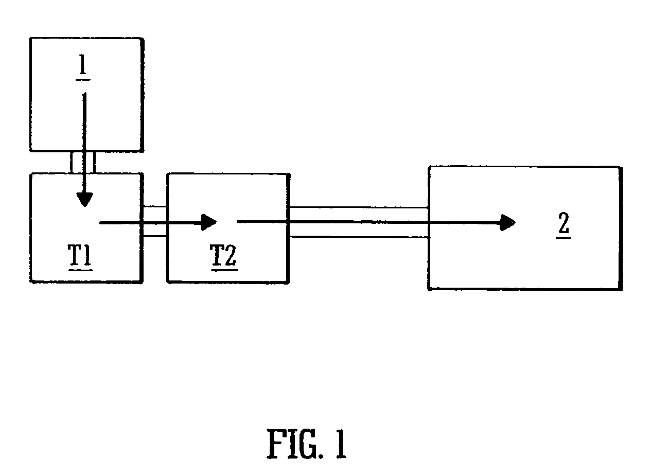
[0140]A preferred embodiment of the present invention will now be described with reference to FIG. 1. FIG. 1 shows an embodiment wherein two ion traps T1, T2, for example 3D (Paul) quadrupole ion traps, are arranged in series to provide an ion trapping system having an improved overall mass range. The ion trapping system is arranged to receive ions from an ion source 1. However, the ions may not necessarily be generated externally to the first ion trap T1 and according to another embodiment described in more detail later, ions may be generated or formed within the first ion trap T1.

[0141]If ions are generated externally to the first ion trap T1 then they are preferably transferred from the ion source 1 into the first ion trap T1 using inhomogeneous RF confining fields. For example, an RF ion guide may be provided and an axial DC electric field gradient and / or travelling DC voltages or voltage waveforms (i.e. wherein axial trapping regions are translated along the length of an ion gu...


PUM


Abstract

A mass spectrometer is disclosed comprising an ion trap ion source wherein a microtitre sample or target plate forms part of one end-cap electrode.

Description

CROSS-REFERENCE TO RELATED APPLICATION[0001]This application claims the benefit of the filing of U.S. Provisional Patent Application Ser. No. 60 / 422,088, filed Oct. 30, 2002.BACKGROUND OF THE INVENTION[0002]1. Field of the Invention[0003]The present invention relates to a mass spectrometer and a method of mass spectrometry. The preferred embodiment relates to 3D quadrupole ion traps (“QIT”) and Time of Flight (“TOF”) mass analysers.[0004]2. Discussion of the Prior Art[0005]Known 3D (Paul) quadrupole ion trap mass spectrometers comprise a doughnut shaped central ring electrode and two end-cap electrodes. Such known 3D (Paul) quadrupole ion trap mass spectrometers typically have a relatively low resolution and a relatively low mass measurement accuracy when scanning the complete mass range compared with other types of mass spectrometers such as magnetic sector and Time of Flight mass spectrometers. 3D quadrupole ion traps do however exhibit a relatively high sensitivity in both MS and...

Claims


Application Information

Patent Timeline
IPC IPC(8): H01J49/04H01J49/42
CPCH01J49/424H01J49/0418
Inventor BATEMAN, ROBERT HAROLDBROWN, JEFF
Owner MICROMASS UK LTD
Why Eureka
Try Eureka