Ball-worm transmission

a technology of worms and balls, applied in mechanical equipment, gearing, hoisting equipment, etc., can solve the problems of reduced power transmission efficiency, and inability to manufacture, so as to improve the performance of a number of balls, simple manufacturing, and the effect of superior performan

Inactive Publication Date: 2006-05-30
HOLTZ DOUGLAS
View PDF24 Cites 84 Cited by
  • Summary
  • Abstract
  • Description
  • Claims
  • Application Information

AI Technical Summary

Benefits of technology

[0012]According to the structure of the present invention, the worm geometry is hyperboloidal for obtaining superior performance by simultaneous engagement of multiple gear teeth. The invention also augments a number of balls and includes a ball recirculation path.
[0013]With these modifications the worm and the gear are no longer in contact, yet, at any instance of time they both contact several balls. The rotation of the worm causes the balls between the worm and the gear to roll, thus causing the gear to follow the worm rotation, with a given transmission ratio. Rolling out of the common contact zone between the worm and gear, balls are being recycled on a special circulation path enclosed within the worm. The recirculation path has been designed to provide smooth recirculation while allowing simple manufacturing by constructing the worm of two concentric components.
[0014]The classic worm transmission uses the sliding friction between the worm and the gear to implement rotational transfer. The present invention replaces the sliding friction of the classic worm mechanism with the rolling friction of spherical balls. Several major advantages result from the friction reduction: minimal backlash, kinematic precision, high efficiency, increased power transmission capability, minimal lubrication requirement, and the possibility to be designed in backdrive or non-backdrive configurations. The ball worm transmission of the present invention, moreover, may implement high transmission ratios in a manner similar to the classic worm transmission, and the design of the ball worm transmission of the present invention also allows for the miniaturization of the transmission assembly.

Problems solved by technology

Each particular approach either presents limited non-backlash torque ranges or is too complex to be miniaturized.
Moreover, these solutions present reduced power transmission efficiency (typically on the order of 30%).
Its only problem is that it may not be constructed without backlash and it is power inefficient.
In practice this perfect condition is impossible to achieve due to misalignment and manufacturing errors.
Moreover, this is impossible to maintain due to the wear of the surfaces under sliding friction.
Therefore, in case a clearance is present, the transmission presents backlash, the worm gear plays.
If interference is present, the friction forces are highly increased and the transmission is either blocked or very inefficient creating premature wearing.
Furthermore, it is common that the worm and the gear are not perfectly mounted on their shafts so that they are eccentric.
This causes the gear to present variable clearance or interference at different angular positions, consequently the transmission does not exhibit uniform performance, is kinematically inconsistent, and imprecise.
Thus, although the classic worm transmission is simple, non-backdrivable, and may be miniaturized, its sliding friction causes reduced efficiency and kinematic inconsistency.

Method used


Image

  • Ball-worm transmission
  • Ball-worm transmission
  • Ball-worm transmission

Examples


Embodiment Construction

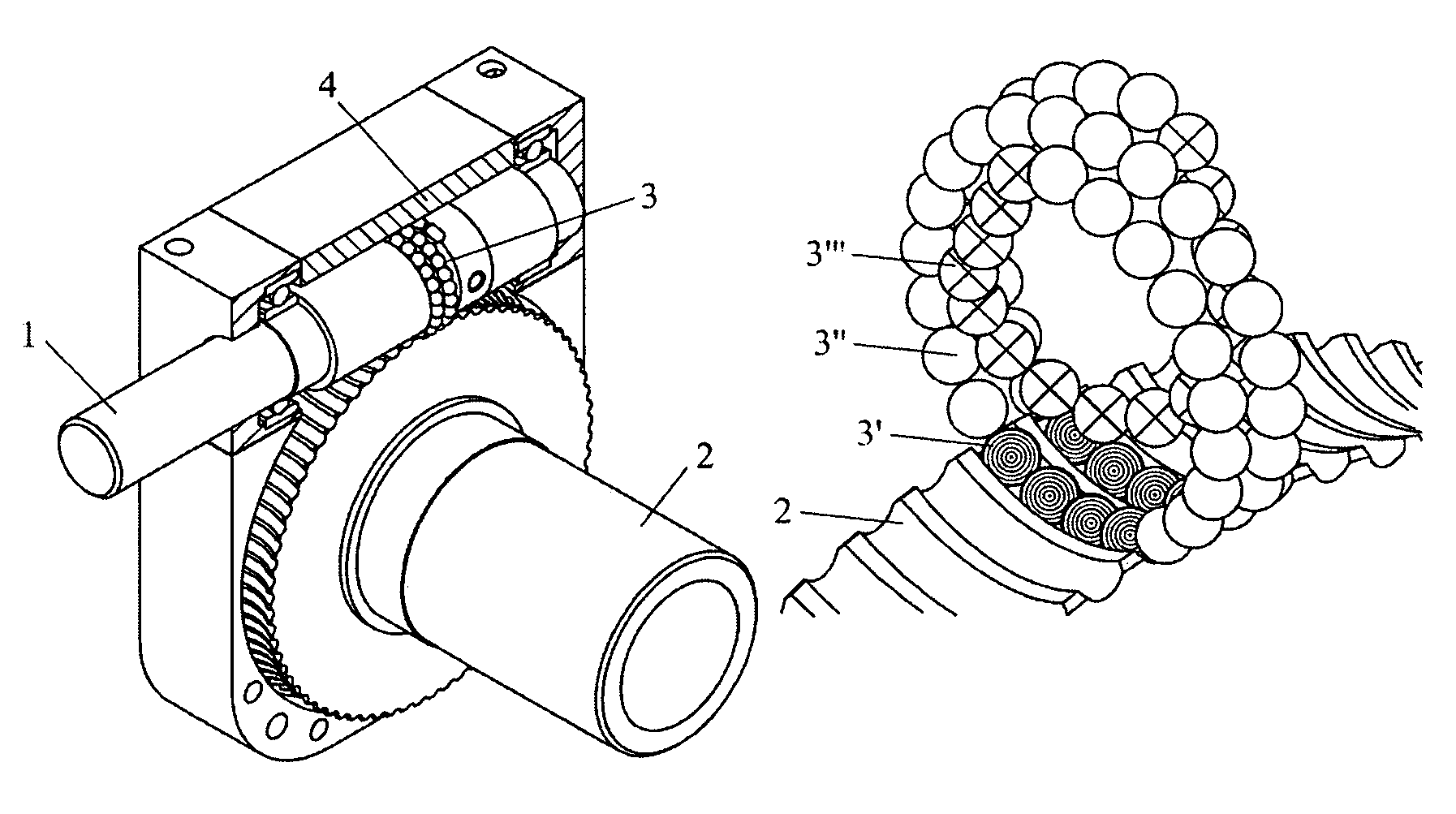
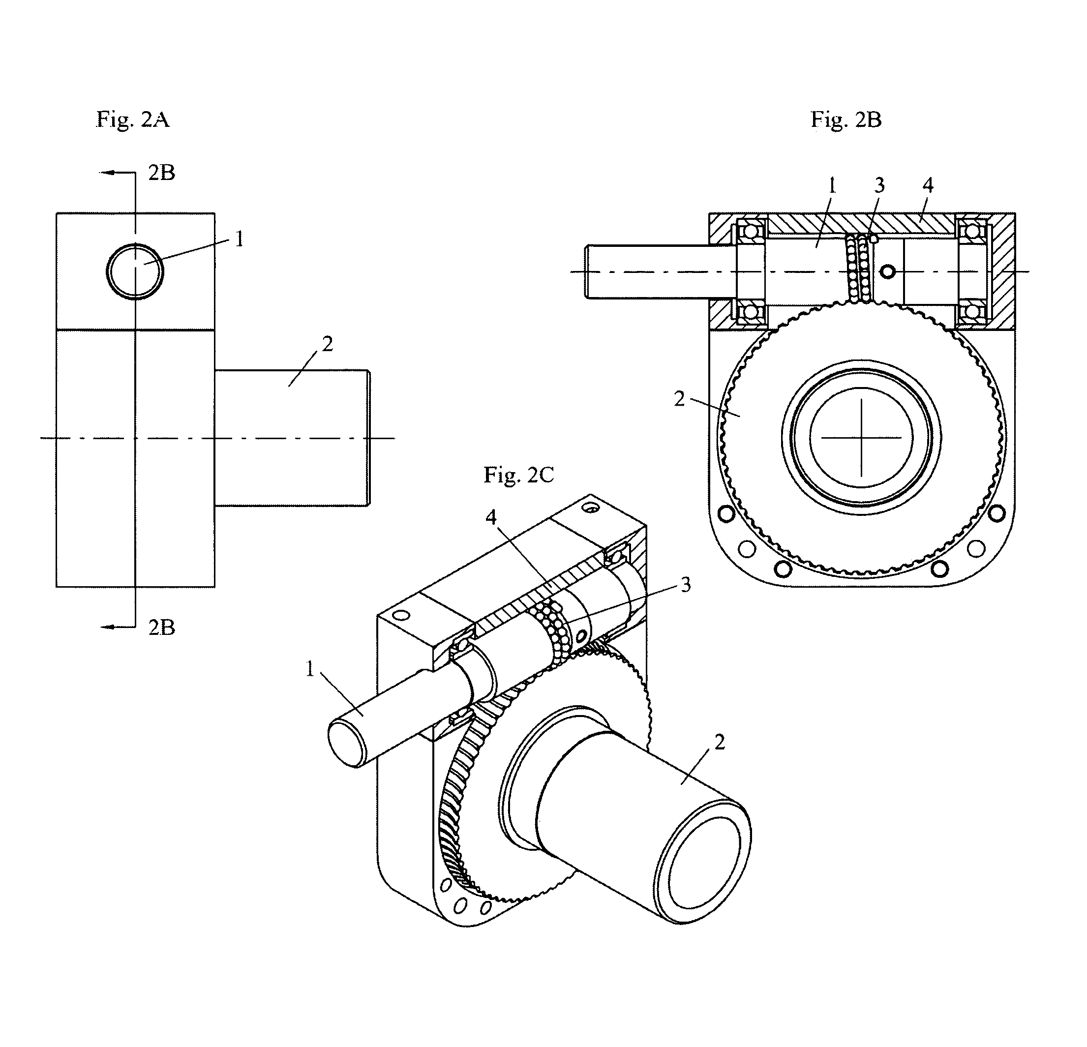
[0040]A schematic of the ball-worm transmission assembly is shown in FIG. 2. The transmission comprises a worm 1, a gear 2, a finite number of spherical balls 3, and casing assembly or ball race 4 including some bearings of the shafts. The ball recirculation mechanism is implemented into the worm 1, which is constructed of two concentric parts that are fixed one to another. The balls are recycled through the inner part of the worm.

[0041]As shown in FIGS. 3A, 3B and 3C, the worm 1 and the gear 2 are not in direct contact. The motion transfer is realized through the balls 3 that roll between them. The worm helix and the gear teeth present a special geometry of double-circular undercut profile (see FIG. 21).

[0042]A recirculation path is implemented on the worm assembly. Several balls are in contact between the worm and the gear at any position of the mechanism. A detail of the ball path is shown in FIGS. 4A, 4B and 4C. For clarity, in this schematic the worm has been hidden. The balls ...


PUM


Abstract

A ball-worm transmission is provided which replaces the sliding friction of the classic worm mechanism with the rolling friction of spherical balls. The ball-worm transmission assembly includes a worm which defines a recirculation path, and a gear coupled to the worm via a plurality of spherical balls. The gear includes a plurality of teeth each having a thickness in a central plane of the gear and a lesser thickness towards both sides of the gear, so that a gap is defined between the teeth is larger towards both sides of the gear than in the central plane of the gear.

Description

[0001]This application claims the benefit of U.S. Provisional Application No. 60 / 339,247 filed Nov. 13, 2001, the entire contents of which are incorporated herein by reference.BACKGROUND OF THE INVENTION[0002]The present invention relates to a ball worm transmission for transmission of rotational motion between two shafts with nonintersecting axes using rolling elements. It represents a combination of two mechanical principles: the worm transmission and the rolling of spherical balls. The functionality is somewhat similar to a ball-screw mechanism; however it provides a rotational rather than translational output.[0003]The invention resulted from the need for a miniature, kinematically precise, highly efficient rotational transmission with high transmission ratio capable of transmitting relatively high power with no backlash. Such mechanisms are required for actuating revolute joints of precision mechanisms such as small robot manipulators.[0004]Several solutions for creating non-ba...

Claims


Application Information

Patent Timeline
Patent Type & Authority Patents(United States)
IPC IPC(8): F16H27/02F16C29/06F16H1/16F16H1/20F16H19/04F16HF16H1/00F16H55/24
CPCF16H1/163Y10T74/19763Y10T74/19828Y10T74/18792Y10T74/19953
Inventor STOIANOVICI, DANKAVOUSSI, LOUIS
Owner HOLTZ DOUGLAS
Why Eureka
Try Eureka