Spin-valve thin-film magnetic element and method for making the same

a thin-film magnetic element and spin-valve technology, applied in the field of spin-valve thin-film magnetic elements, can solve the problems of reducing the detection sensitivity, difficult to precisely define the effective magnetic recording track width, and reducing the recording density, so as to enhance the exchange coupling magnetic field, and stable state

Inactive Publication Date: 2006-05-30
ALPS ALPINE CO LTD
View PDF11 Cites 6 Cited by
  • Summary
  • Abstract
  • Description
  • Claims
  • Application Information

AI Technical Summary

Benefits of technology

[0047](6) To improve the detection sensitivity of the spin-valve thin-film magnetic element;
[0109]In the method for making the spin-valve thin-film magnetic element, a heat resistant alloy, such as a PtMn alloy, is used for not only the antiferromagnetic layer but also the exchange bias layer, and an exchange anisotropic magnetic field can be generated in the exchange bias layer for aligning the magnetization vector of the free magnetic layer in a direction orthogonal to the magnetization vector of the pinned magnetic layer without adversely affecting the magnetization vector of the pinned magnetic layer. The resulting spin-valve thin-film magnetic element exhibits high heat resistance and outputs signals having highly symmetrical waveforms.

Problems solved by technology

Since the width of the insensitive region varies, it is difficult to precisely define the effective magnetic recording track width.
When the initial magnetic recording track width Tw is set smaller, the rate of change in resistance (ΔR / R) in the GMR effect decreases, resulting in degradation of the detection sensitivity.
With the degraded detection sensitivity, it is difficult to improve the recording density.
This is especially problematic because, since the width and the intervals of the recording tracks on the magnetic recording medium are decreased to achieve higher recording density, the lateral portions 125s may read-out the information on the adjacent track relative to the magnetic recording track which the sensitive region should have had read.
This problem of side—reading may generate noise in the output signals, causing errors.
Thus, the effective track width cannot be controlled precisely, and the detection precision is degraded.
This is problematic especially in spin-valve thin-film magnetic elements designed for use with magnetic recording track width of 0.5 μm or less.
Such a difference in the free magnetic layer 125 may inhibit the free magnetic layer 125 from being in a single-magnetic-domain state as if there is a magnetic wall inside, the magnetization vectors become non-uniform, and Barkhausen noise may be generated causing instability and errors in processing the signals provided from the magnetic recording medium.
An increase in asymmetry causes degradation in the output characteristics of the spin-valve thin-film magnetic element.
However, these configurations also suffer from the above-described problems.

Method used


Image

  • Spin-valve thin-film magnetic element and method for making the same
  • Spin-valve thin-film magnetic element and method for making the same
  • Spin-valve thin-film magnetic element and method for making the same

Examples


first embodiment

[0137]A first embodiment of the spin-valve thin-film magnetic element and a method for making the spin-valve thin-film magnetic element in accordance with the present invention will be described below with reference to the attached drawings.

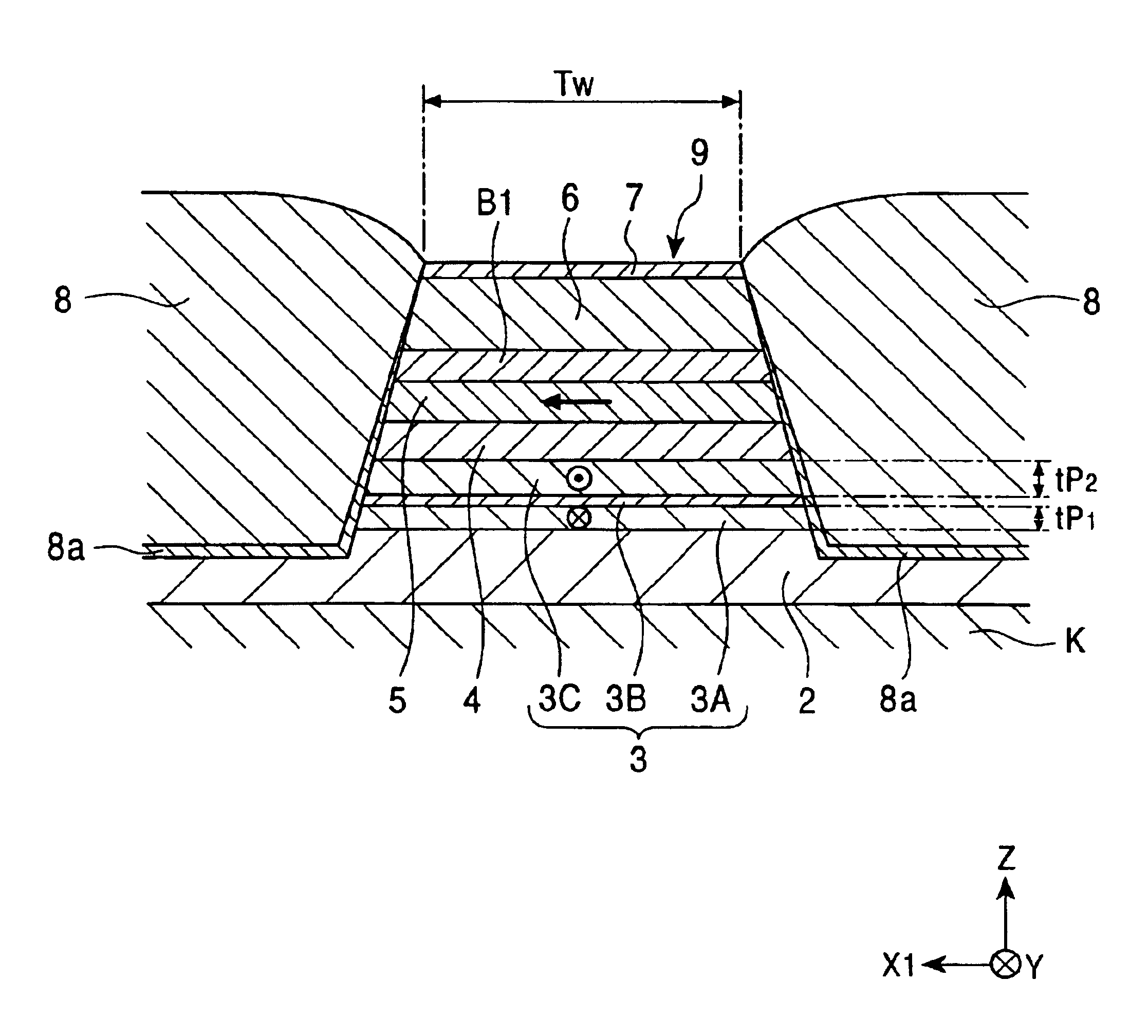
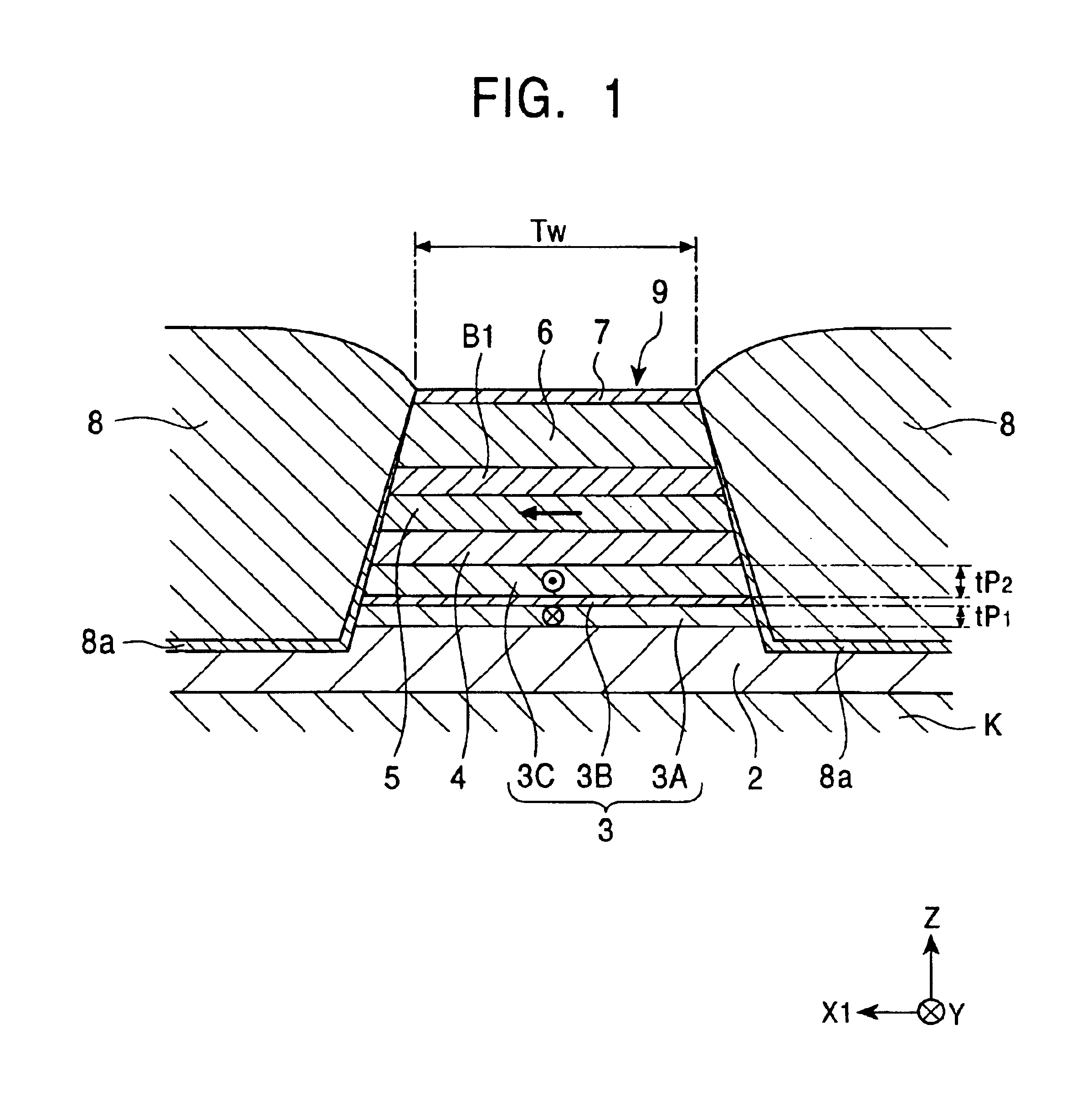
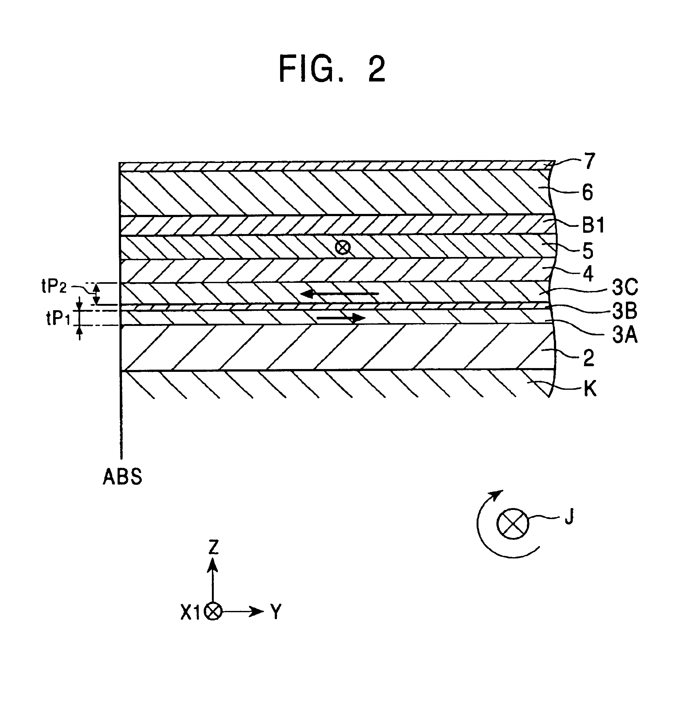
[0138]FIG. 1 is a cross-sectional view of the first embodiment of the spin-valve thin-film magnetic element in accordance with the present invention when viewed from a face opposing a recording medium. FIG. 2 is a cross-sectional view illustrating the structure of the spin-valve thin-film magnetic element in FIG. 1 in the height direction.

[0139]The spin-valve thin-film magnetic element of the present invention is of a type in which a giant magnetoresistive (GMR) element utilizes a giant magnetoresistive effect. This spin-valve thin-film magnetic element is, as will be described below, typically disposed at the trailing end face of a floating slider provided in a hard disk device so as to detect the recording magnetic field of a hard disk or the l...

second embodiment

[0359]A second embodiment of the spin-valve thin-film magnetic element, the method for making the same, and the thin-film magnetic head provided with the spin-valve thin-film magnetic element will now be described with reference to FIG. 5, which is a cross-sectional view of the spin-valve thin-film magnetic element, viewed from a recording medium.

[0360]This spin-valve thin-film magnetic element is also of a bottom type. That is, a composite 9 include an antiferromagnetic layer 2, a pinned magnetic layer 3, a nonmagnetic conductive layer 4, and a free magnetic layer 5 which are formed, in that order, on a substrate K, as in the first embodiment shown in FIGS. 1 to 4. The pinned magnetic layer 3 is composed of a first pinned magnetic sublayer 3A and a second pinned magnetic sublayer 3C, separated by a nonmagnetic interlayer 3B. The magnetization vectors of the first and second pinned magnetic sublayers 3A and 3C, respectively, are antiparallel to each other. Thus, this spin-valve thin...

third embodiment

[0404]A third embodiment of the spin-valve thin-film magnetic element, the method for making the same, and the thin-film magnetic head provided with the spin-valve thin-film magnetic element will now be described with reference to FIG. 6, which is a cross-sectional view of the spin-valve thin-film magnetic element, viewed from a recording medium.

[0405]This spin-valve thin-film magnetic element is of a top type. That is, a composite 19 having substantially a trapezoidal cross section include an underlying layer 11 composed of tantalum or the like, an exchange bias layer 16, a back layer B2 as a mean-free-path-extending layer, a free magnetic layer 15, a nonmagnetic conductive layer 14, a pinned magnetic layer 13, an antiferromagnetic layer 12, and a protective layer 17, which are formed, in that order, on a substrate K. Electrode layers 18 are provided on two sides of the composite 19.

[0406]The pinned magnetic layer 13 is divided into a first pinned magnetic sublayer 13A and a second...


PUM

PropertyMeasurementUnit
thicknessaaaaaaaaaa
thicknessaaaaaaaaaa
total thicknessaaaaaaaaaa

Abstract

A spin-valve thin-film magnetic element includes a substrate, a composite formed thereon, and electrode layers formed on both sides of the composite. The composite includes an antiferromagnetic layer, a pinned magnetic layer, a nonmagnetic conductive layer, a free magnetic layer, a mean-free-path-extending layer, and an exchange bias layer. The mean-free-path-extending layer may be a back layer or a mirror reflective layer. The mean-free-path-extending layer extends the mean free path of spin-up conduction electrons in the spin-valve thin-film magnetic element. This spin-valve thin-film magnetic element meets trends toward a narrower track width.

Description

BACKGROUND OF THE INVENTION[0001]1. Field of the Invention[0002]The present invention relates to a spin-valve thin-film magnetic element which undergoes a change in electrical resistance in relation to the magnetization vector of a pinned magnetic layer and the magnetization vector of a free magnetic layer affected by an external magnetic field, and to a thin-film magnetic head provided with the spin-valve thin-film magnetic element. In particular, the present invention relates to a technology suitable for a spin-valve thin-film magnetic element which includes a free magnetic layer having improved soft magnetic characteristics and thus exhibits an enhanced rate of change in resistance.[0003]2. Description of the Related Art[0004]A spin-valve thin-film magnetic element is a type of giant magnetoresistive element (GMR) exhibiting a giant magnetoresistive effect and detects recorded magnetic fields from a recording medium such as a hard disk. Among GMRs, the spin-valve thin-film magnet...

Claims


Application Information

Patent Timeline
Patent Type & Authority Patents(United States)
IPC IPC(8): G11B5/127G01R33/09G11B5/39H01F10/06H01F10/08H01F10/32H01F41/22H01F41/30H01L43/08H01L43/12
CPCB82Y10/00B82Y25/00B82Y40/00G11B5/3903H01F10/3268H01F41/302H01F41/325Y10T29/49034Y10T29/49044G11B2005/3996
Inventor HASEGAWA, NAOYAHONDA, KENJIKAKIHARA, YOSHIHIKO
Owner ALPS ALPINE CO LTD
Why Eureka
Try Eureka