
Sulfur deposition control method and related control algorithm

a control method and sulfur technology, applied in the field of sulfur deposition, can solve the problems of gas emission compliance loss, unwanted changes in gas combustion, and reduction of turbine load capacity, and achieve the effect of preventing sulfur deposition, reducing the minimum required energy usage or loss of efficiency of the gas turbin

Active Publication Date: 2006-06-06
GENERAL ELECTRIC CO
View PDF4 Cites 9 Cited by
  • Summary
  • Abstract
  • Description
  • Claims
  • Application Information

AI Technical Summary

Benefits of technology

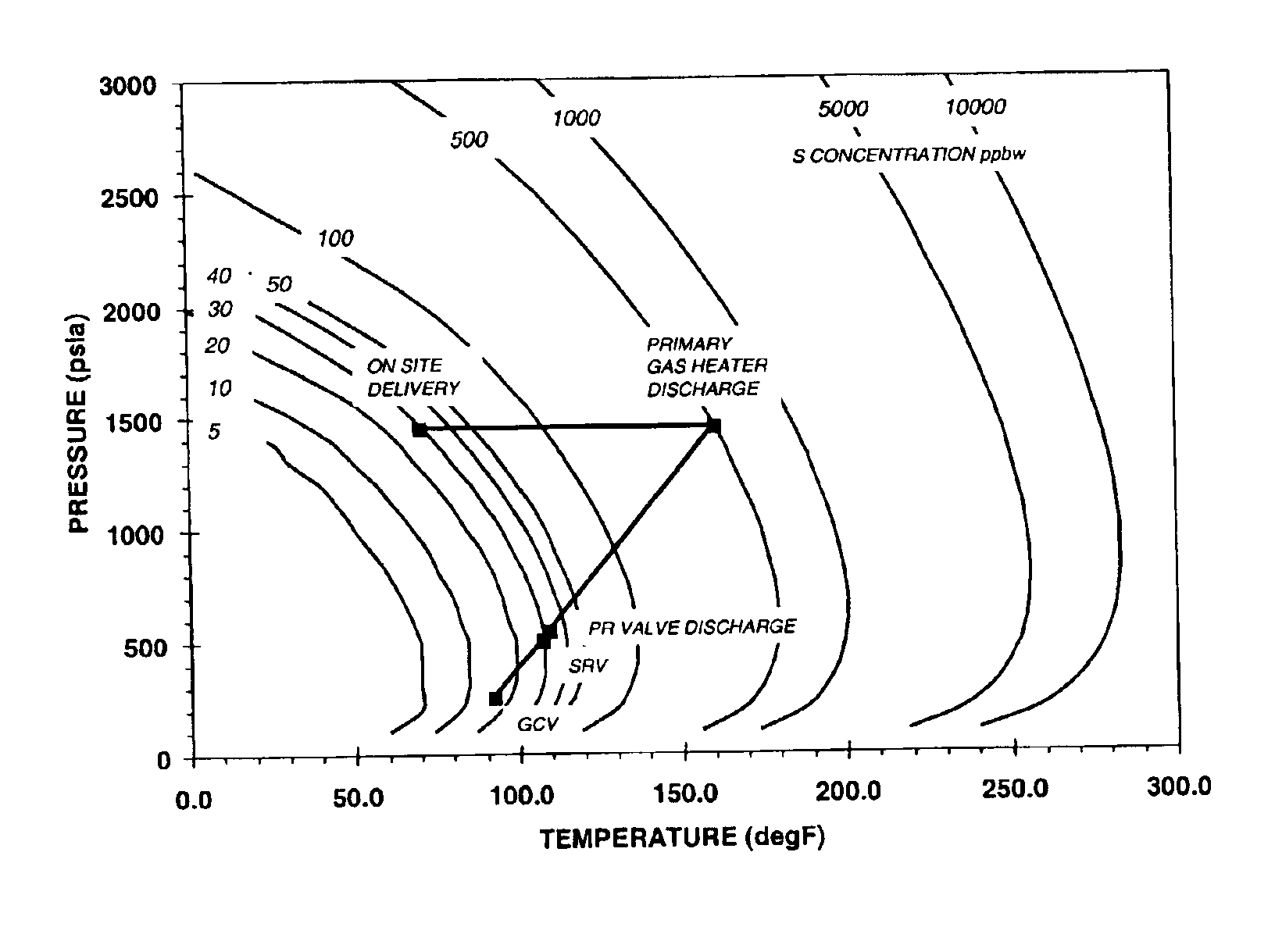
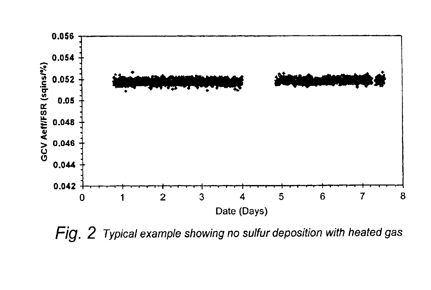
[0008]The present invention addresses the sulfur deposition problems identified in the prior art by preventing the formation of sulfur deposits in pressure reducing valves in both the valve throat and in downstream valves and piping. The invention achieves that objective in conventional gas processing systems using a unique gas control algorithm. Upon implementation, the algorithm eliminates the need for forced outages required to clean gas processing equipment at the deposit site. The method according to the invention also prevents sulfur deposition with a minimum required energy usage or loss of efficiency of the gas turbine.

Problems solved by technology

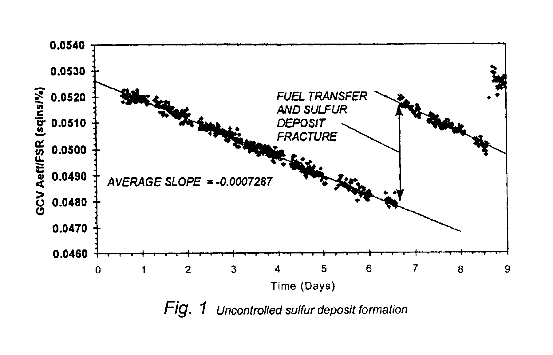
If the deposits are allowed to continue, the valves eventually reach 100% open and further deposition results in a reduction in turbine load capacity, as well as unwanted changes in gas combustion and a loss of gas emission compliance.
This conventional solution to sulfur deposition can be unreliable, however, and has resulted in fuel nozzle plugging and hardware damage.
Such cleaning operations are labor intensive requiring several days of forced outage of the gas turbine and significant loss of income to the end user.
The very low concentration of elemental sulfur vapor contained in the incoming gas feed, typically 20-30 parts per billion by weight (ppbw), make it impractical for plant operators to impose stringent fuel specifications on gas suppliers to completely eliminate the presence of sulfur in the feed gas.
Concentrations of such small magnitude cannot be measured by commercially available equipment.

Method used


Image

  • Sulfur deposition control method and related control algorithm
  • Sulfur deposition control method and related control algorithm
  • Sulfur deposition control method and related control algorithm

Examples


Embodiment Construction

[0015]The present invention relies on two basic methodologies, both of which directly relate to the subject gas control algorithm. The two methods include a sulfur detection method and temperature control system.

[0016]The sulfur detection method used in accordance with the invention relies on the fact that the GCV's operate in the choked flow mode, that is, the pressure drop across the valves is such that the flow through the valves is proportional only to the upstream pressure, temperature, gas properties and effective valve area. A similar method can be used for non-critical valves, provided the upstream and downstream pressures are known.

[0017]The gas fuel specific heat ratio is determined from the measured gas fuel composition from which the choking pressure ratio is calculated. Given the choking pressure ratio, the upstream pressure and temperature and the gas mass flow rate, the GCV effective area can be accurately determined. The feedback control signal from the GCV's is meas...


PUM


Abstract

A method for detecting and controlling the elemental sulfur deposition on pressure reducing gas fuel control valves in cases where the sulfur deposition results from a temperature drop during expansion across the control valve, such as that encountered in gas turbine engines. The control method and algorithm according to the invention uses measured parameters of gas flow rate, pressure and temperature, combined with known pressure reducing valve characteristics to first determine whether sulfur deposition has occurred, and thereafter to calculate a valve position control parameter used to control the gas temperature upstream of the control valve, thereby maintaining the sulfur in a vapor phase through the pressure reducing process and preventing subsequent sulfur deposition on the valve and downstream piping.

Description

[0001]The present invention relates to a method for detecting and controlling elemental sulfur deposition on pressure reducing gas fuel control valves. In particular, the invention relates to the development of a new control algorithm that can be used to reduce the amount of sulfur deposition in the gas fuel control valves on gas turbine engines that are used, for example, in the generation of electricity. The control algorithm can also be used in non-turbine applications where sulfur deposition results from a temperature drop during vapor expansion analogous to that encountered in gas turbine engines.[0002]The control method and algorithm according to the invention uses known parameters of gas flow rate, pressure and temperature combined with known pressure reducing valve characteristics to determine whether sulfur deposition has taken place. Once the fact of sulfur deposition is confirmed, a control signal is passed to an electrical (or equivalent) gas heater to raise the gas temp...

Claims


Application Information

Patent Timeline
IPC IPC(8): G01F1/00F02C7/224F02C7/232F02C9/28
CPCF02C7/224F02C9/28F02C7/232
Inventor WILKES, COLIN
Owner GENERAL ELECTRIC CO
Learn More