Method for driving liquid-jet head and liquid-jet apparatus

a liquid-jet head and liquid-jet technology, applied in the direction of printing, other printing apparatus, etc., can solve the problems of difficult cutting of the head, complicated manufacturing process, and difficulty in achieving the high density array of piezoelectric elements, and achieve high density array and high quality printing

Active Publication Date: 2006-06-06
SEIKO EPSON CORP
View PDF5 Cites 10 Cited by
  • Summary
  • Abstract
  • Description
  • Claims
  • Application Information

AI Technical Summary

Benefits of technology

[0017]According to the first aspect of the invention, the piezoelectric element having the piezoelectric layer consisting of the relaxor ferroelectric is driven by the use of a drive voltage within a predetermined range. As a result, desired distortional deformation can be caused to the piezoelectric element at a low voltage and a low current, and a high density array and multi-nozzle arrangement can be achieved without destruction of the drive IC or the wiring.
[0034]According to the eighth aspect of the invention, the piezoelectric element having the piezoelectric layer consisting of the relaxor ferroelectric is driven by the use of a drive voltage within a predetermined range. As a result, desired distortional deformation can be caused to the piezoelectric element at a low voltage and a low current, and a high density array and multi-nozzle arrangement can be achieved without destruction of the drive IC or the wiring. Consequently, high quality printing can be achieved.

Problems solved by technology

However, this recording head requires a difficult step of cutting and dividing the piezoelectric element in a comb tooth shape in conformity with the array pitch of the nozzle orifices, and also requires an operation for aligning and fixing the divisions of the piezoelectric element to the pressure generating chambers.
Consequently, the manufacturing process is complicated.
However, a certain size of the vibration plate is required because of the usage of flexural vibration, thus posing difficulty in achieving a high density array of the piezoelectric elements.
This high current destroys the driving IC and driving wiring, thus posing the problem that a high density array of the piezoelectric elements and multiple-nozzle arrangement are difficult to attain.
This problem is not limited to the ink-jet recording head for ejection of ink.
Needless to say, the problem exists similarly with other liquid-jet heads for ejection liquids other than ink.

Method used


Image

  • Method for driving liquid-jet head and liquid-jet apparatus
  • Method for driving liquid-jet head and liquid-jet apparatus
  • Method for driving liquid-jet head and liquid-jet apparatus

Examples


embodiment 1

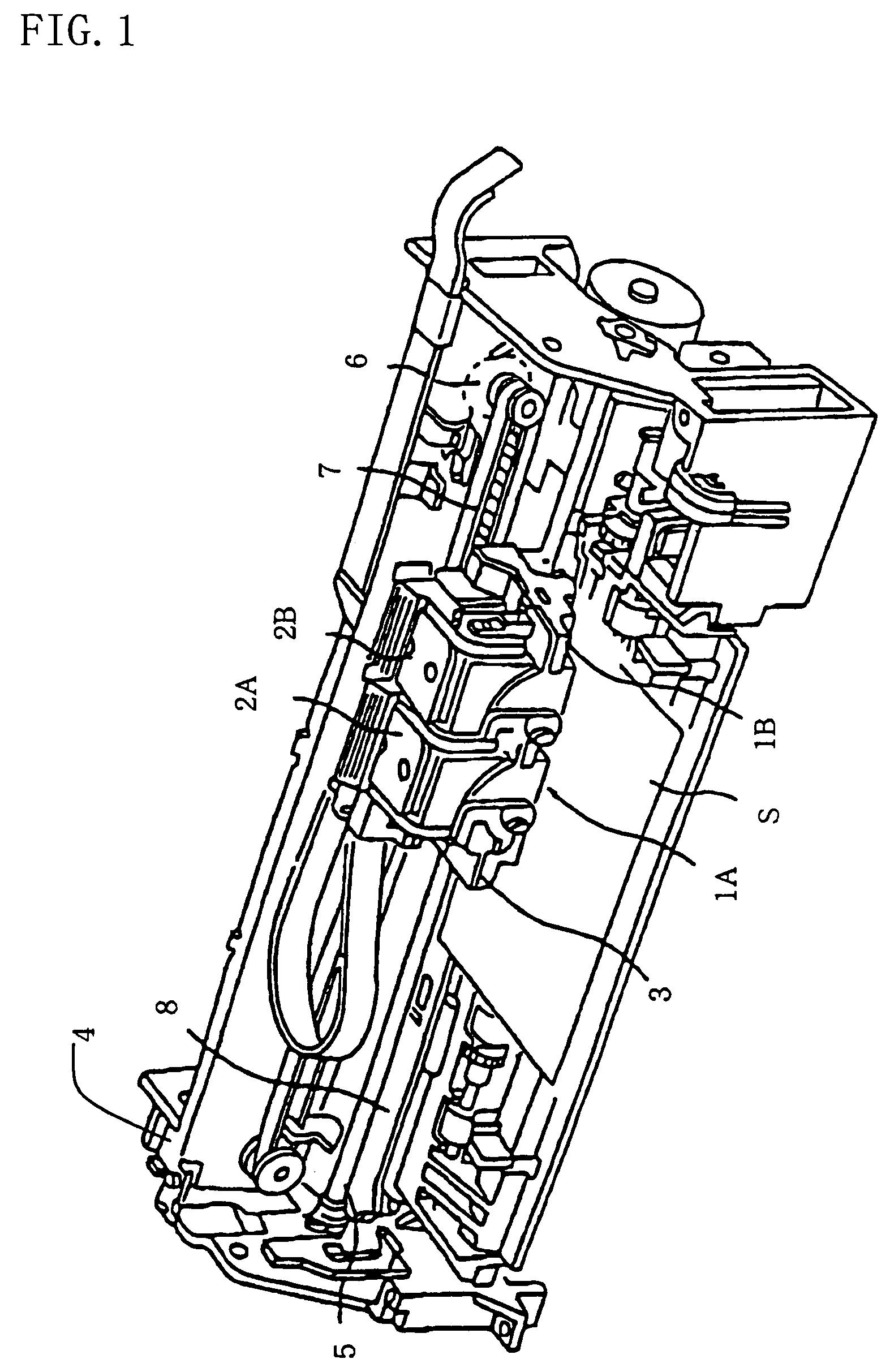
[0044]FIG. 1 is a schematic view showing an example of the liquid-jet apparatus according to Embodiment 1. In jet head units 1A and 1B which have liquid-jet heads, as shown in FIG. 1, cartridges 2A and 2B constituting liquid supply means are detachably provided. A carriage 3 having the jet head units 1A and 1B mounted thereon is provided on a carriage shaft 5, which is attached to an apparatus body 4, so as to be movable in the axial direction. The jet head units 1A and 1B are adapted to eject, for example, a black ink composition and a color ink composition, respectively, as liquids.

[0045]The driving force of a drive motor 6 is transmitted to the carriage 3 via a plurality of gears (not shown) and a timing belt 7, whereby the carriage 3 bearing the jet head units 1A and 1B is moved along the carriage shaft 5. On the other hand, a platen 8 is provided on the apparatus body 4 along the carriage shaft 5. A recording sheet S, a recording medium, such as paper, fed by a paper feeding ro...


PUM


Abstract

Disclosed is a method for driving a liquid-jet head comprising a passage-forming substrate in which pressure generating chambers communicating with nozzle orifices are formed; and a piezoelectric element provided on one surface of the passage-forming substrate via a vibration plate, and consisting of a lower electrode, a piezoelectric layer, and an upper electrode. The piezoelectric layer consists of a relaxor ferroelectric. A voltage between a potential V1, at which the capacitance of the piezoelectric element is maximal in a capacitance-potential curve of the piezoelectric element, and a potential V2, which has a larger absolute value than the absolute value of the potential V1 and at which an inflection point in the capacitance-potential curve is reached, is set as a drive start potential V0. The piezoelectric element is driven using a drive waveform having an ejection step for changing the potential from the drive start potential V0 to a potential V3, at which a driving electric field having an electric field strength of 100 to 500 kV / cm is generated in the piezoelectric layer, to contract the pressure generating chamber, thereby ejecting liquid droplets through the nozzle orifice.

Description

BACKGROUND OF THE INVENTION[0001]1. Field of the Invention[0002]This invention relates to a method for driving a liquid-jet head in which a portion of a pressure generating chamber communicating with a nozzle orifice for jetting a liquid is constituted of a vibration plate, a piezoelectric element is formed on the surface of the vibration plate, and the liquid is jetted by displacement of the piezoelectric element, and a liquid-jet apparatus equipped with the liquid-jet head.[0003]2. Description of the Related Art[0004]An example of a liquid-jet apparatus is an ink-jet recording apparatus comprising an ink-jet recording head equipped with a plurality of pressure generating chambers for generating pressure for ejection of ink droplets by piezoelectric elements or heating elements; a common reservoir for supplying ink to the respective pressure generating chambers; and nozzle orifices communicating with the respective pressure generating chambers. This ink-jet recording apparatus appl...

Claims


Application Information

Patent Timeline
Patent Type & Authority Patents(United States)
IPC IPC(8): B41J29/38B41J2/045B41J2/055
CPCB41J2/04581B41J2/04541B41J2/04588B41J2002/14241
Inventor SUMI, KOJI
Owner SEIKO EPSON CORP
Why Eureka
Try Eureka