Heat generating resistant element film, substrate for ink jet head utilizing the same, ink jet head and ink jet apparatus

a technology of resistance element and thermal print head, which is applied in the direction of printing, etc., can solve the problems of trouble, serious ink discharge problem, heat generation resistance element employed in thermal print head, etc., and achieve stable ink discharge and high quality

Inactive Publication Date: 2006-06-06
CANON KK
View PDF15 Cites 3 Cited by
  • Summary
  • Abstract
  • Description
  • Claims
  • Application Information

AI Technical Summary

Benefits of technology

[0031]A principal object of the present invention is to solve aforementioned drawbacks associated with the conventional material for the heat generating resistant element of the ink jet recording head, and to provide a heat generating resistant element film adapted for use as a heat generating resistant element allowing to obtain a recorded image of a high quality over a prolonged period and a producing method therefor. Another object of the present invention is to provide an ink jet apparatus having, as a heat generating resistant element of an electrothermal converting member, a heat generating resistant element film enabling a stable ink discharge even in case of a smaller dot discharge for realizing a recorded image of a higher definition or a high-speed drive for realizing a high-speed recording, an ink jet head substrate to be employed in such configuration and a producing method therefor.
[0052]According to the present invention, there can be provided a heat generating resistant element film as a material for the heat generating resistant element, which has an excellent thermal response in a drive utilizing a relatively short pulse, is capable of providing a high sheet resistance and is adapted for a further miniaturization of the heater size. Also by employing such heat generating resistant element film in a heat generating resistant element of the electrothermal converting member, it is possible to provide an ink jet apparatus, an ink jet head to be employed therein and a substrate for constituting such ink jet head, capable of enabling stable ink discharge even in case of a smaller dot for a higher definition of the recorded image or a high-speed drive for a high-speed recording, and reducing the electric current consumption in the drive thereby contributing to energy saving.
[0054]The heat generating resistant element of the ink jet recording head of the present invention can maintain desired durability even in case of a drive with a short pulse, thereby providing a recorded image of a high quality over a prolonged period. Positive and very small TCR characteristics are considered to significantly contribute to such performance.
[0055]The ink jet recording head of the present invention provides effects of enabling a heat generating resistance property of a high resistance suitable for a smaller dot, and realizing a high energy efficiency thereby suppressing the heat generation and enabling energy saving.

Problems solved by technology

Therefore, in consideration of the discharge and the driving method specific to the ink jet head and different from those in the thermal print head, a matching design (film thickness, heater size, shape etc.) is required for the heat generating resistant element and it is known that the heat generating resistant element employed in the thermal print head is not immediately applicable to the ink jet head.
In such state, the heat generating resistant element reaches a temperature of 600 to 700° C., and an eventual change in the resistance of the resistor in such repetition between the room temperature and the high temperature poses a serious problem in the ink discharge.
More specifically, as the ink jet head is generally driven by a constant voltage drive, a trouble is induced in case the resistance shows a large change during the drive.
For example, a decrease in the resistance significantly reduces the service life of the resistor by an excessive current, while an increase in the resistance reduces the current, eventually failing the ink discharge.
Stated differently, in case the aforementioned TaSiN is used to attain the recently requested sheet resistance of 700 Ω / □ or higher (corresponding to specific resistivity of 3,000 μΩ·cm or higher), there will result inferior TCR characteristics and an insufficient durability.
Also in case the resistance is elevated in this manner, there also results a difficulty in productivity such as a fluctuation in the specific resistivity.
However, these references do not teach nor suggest at all as to which atomic composition of CrSiN film is useful as a heat generating resistant element for the electrothermal converting member of the ink jet head, and a composition capable of also satisfying the durability has not been known at all.

Method used


Image

  • Heat generating resistant element film, substrate for ink jet head utilizing the same, ink jet head and ink jet apparatus
  • Heat generating resistant element film, substrate for ink jet head utilizing the same, ink jet head and ink jet apparatus
  • Heat generating resistant element film, substrate for ink jet head utilizing the same, ink jet head and ink jet apparatus

Examples


examples

[0102]In the following embodiments of the present invention will be explained by examples. However, the present invention is not limited to examples to be explained in the following, but is applicable to a resistor film to be utilized for other application as long as the objects of the present invention can be attained.

experiment 1

[0103](Evaluation of Production Stability of Film)

[0104]An evaluation was made on the production stability of a CrSiN film. Film formations were conducted by varying a nitrogen partial pressure under main sputtering conditions with a target composition of Cr30Si70 (at. %), a power of 350 W and a gas pressure of 0.5 Pa, and there was determined a relationship between the nitrogen partial pressure and the specific resistivity (as to the sputtering apparatus, reference is to be made to FIG. 4). Results are shown in FIG. 6. As will be apparent from the chart, the specific resistivity is approximately proportional with the nitrogen partial pressure up to 0.15% (specific resistivity: up to about 1,700 μΩcm, and increases monotonously to a nitrogen partial pressure up to about 20%. Such relationship shows an increased margin in the variation of the nitrogen partial pressure for the specific resistivity, and indicates that the material is very excellent in terms of stability in a mass produ...

example 1

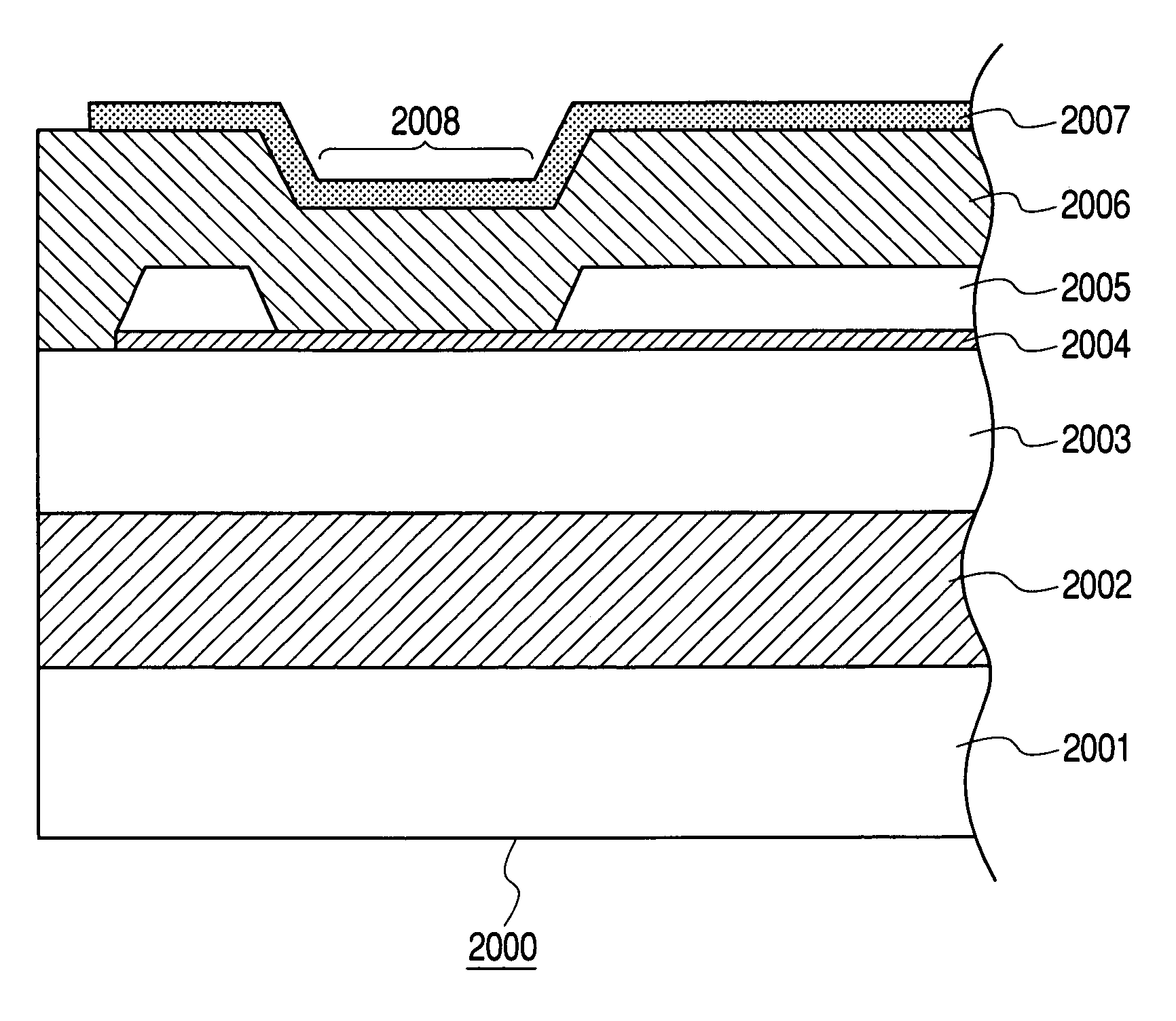
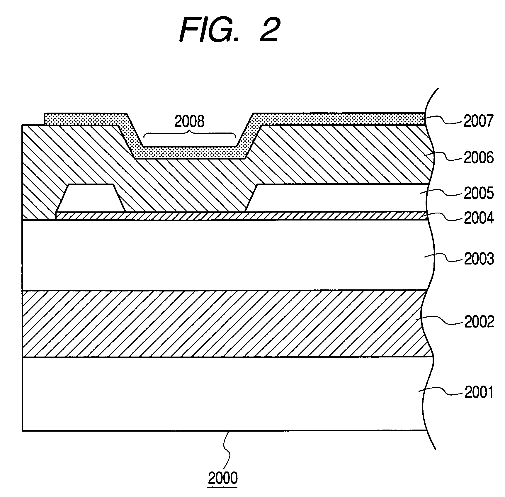
[0107](Preparation of Substrate of Configuration Shown in FIG. 2)

[0108]At first, on a silicon substrate 2001, a heat accumulation layer 2002 of a thickness of 1.8 μm was formed by thermal oxidation, and an SiO2 film, as an interlayer film 2003 serving also as a heat accumulation layer, was formed with a thickness of 1.2 μm by plasma CVD. Then, with the apparatus shown in FIG. 4, a CrSiN film was formed with a thickness of 400 Å as a heat generating resistant element layer 2004.

[0109]This operation was executed with gas flow rates of Ar gas: 64 sccm, and N2 gas: 20 sccm, a power of 350 W charged to the target Cr30Si70, an atmospheric temperature of 200° C. and a substrate temperature of 200° C. Also as a metal wiring 2005 for heating the heat generating resistant element layer 2004 in the heat action surface 2008, an Al—Cu film was formed by sputtering with a thickness of 5,500 Å.

[0110]It was then patterned by a photolithographic process to form a heat action surface 2008 of 15×40 μm...


PUM


Abstract

The invention provides a heat generating resistant element having a high durability and a high resistance suitable for constituting an electrothermal converting member in an ink jet head or an ink jet apparatus. There is employed, as the heat generating resistant element, a film constituted of Cr, Si and N, having a composition of Cr: 15 to 20 at. %, Si: 40 to 60 at. % and N: 20 to 45 at. %, which constitute 100 at. % or substantially 100 at. %.

Description

BACKGROUND OF THE INVENTION[0001]1. Field of the Invention[0002]The present invention relates to a heat generating resistant element film adapted for constituting an electrothermal converting member as generating means for discharging thermal energy for an ink jet apparatus, which discharges ink by an ink jet method for recording or printing a character, a symbol, or an image onto a recording medium constituted of a paper, a plastic sheet, a cloth or another article, an ink jet head substrate and an ink jet apparatus utilizing an electrothermal converting member utilizing such heat generating resistant element film, and a producing method therefor.[0003]2. Related Background Art[0004]An ink jet apparatus has a configuration for discharging a functional liquid for recording etc. (hereinafter representatively called “ink”) from a discharge port onto a recording medium thereby executing a recording of a character, a symbol, an image etc., or an application of a component contained in t...

Claims


Application Information

Patent Timeline
Patent Type & Authority Patents(United States)
IPC IPC(8): B41J2/05B41J2/14B41J2/16
CPCB41J2/14129B41J2/1603B41J2/1646B41J2/1631B41J2/1642B41J2/1604B41J2/05
Inventor SUZUKI, HIROYUKIHAYAKAWA, YUKIHIROKAWASAKI, YOSHINORISAITO, ICHIROYOKOYAMA, SAKAISAKAI, TOSHIYASU
Owner CANON KK
Why Eureka
Try Eureka