Scintillator optical system and method of manufacture

Active Publication Date: 2006-06-06
CARL ZEISS X RAY MICROSCOPY
View PDF3 Cites 85 Cited by
  • Summary
  • Abstract
  • Description
  • Claims
  • Application Information

AI Technical Summary

Benefits of technology

[0030]One of the primary advantages of the present system is its compact size. The electron bombardment source is small, much less expensive, and allows constant access, compared with synchrotron x-ray sources, which are more commonly used for high-resolution x-ray microscopy. A combination of the X-ray radiation train and the optical train ensures that the total size of the X-ray and the optical frequency optics have a size appropriate for laboratory use. For example, if an entirely X-ray optical train is used, with the zone plate lens, the system can meters long, due to the long focal lengths that are common with zone plate lenses.
[0031]In the

Problems solved by technology

The chemical detectors, however, suffer from the properties that they are single-use only and require post-exposure chemical processing to reveal or develop the image.
The photoresists typically have extremely high resolution of a few nanometers, resolution being limited primarily by secondary electron exposure.
These electronic imaging detectors, however, can suffer from radiation damage to the gate circuits.
X-ray radi

Method used


Image

  • Scintillator optical system and method of manufacture
  • Scintillator optical system and method of manufacture
  • Scintillator optical system and method of manufacture

Examples


Embodiment Construction

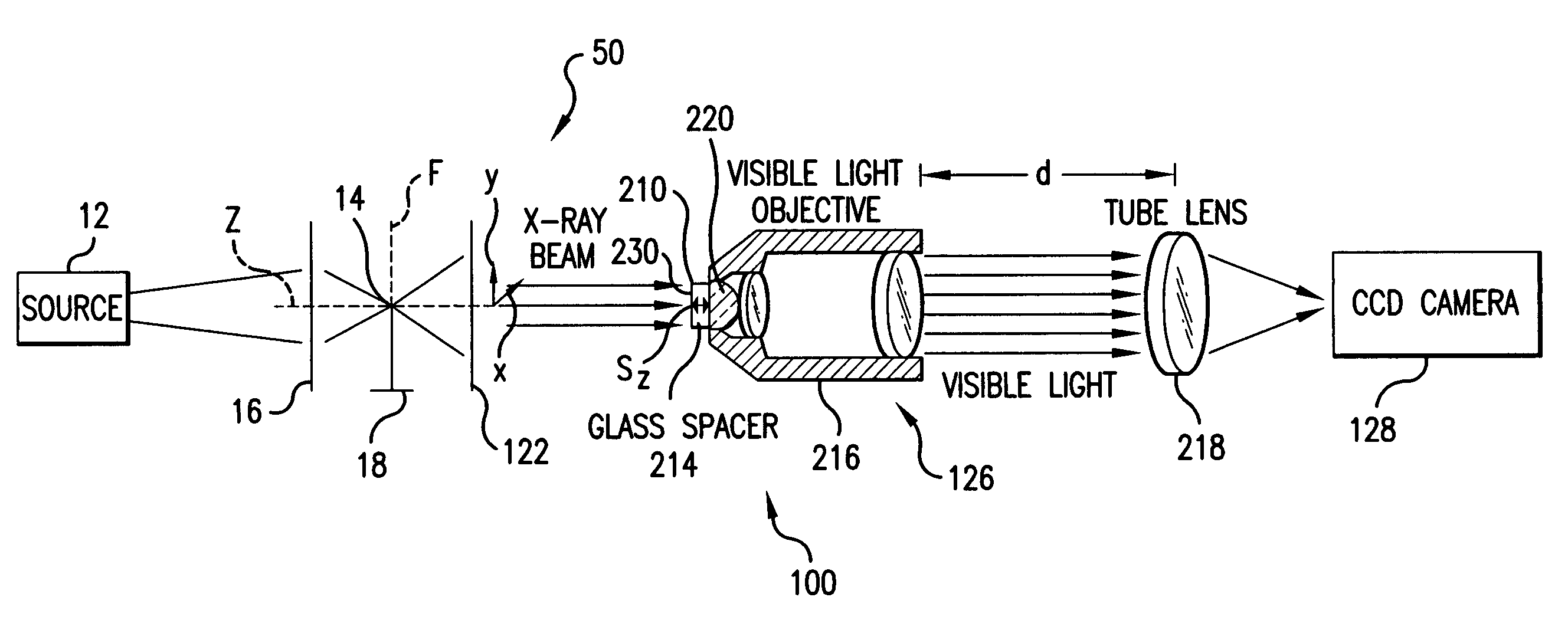
[0038]FIG. 1 shows an X-ray microscope, including a scintillator optical system 100, which have been constructed according to the principles of the present invention.

[0039]Specifically, a sample 14 is located at the system's focal plane f. It is illuminated preferably by hard x rays in 1–20 kilo-electron-Volts (keV) photon energy range. These x-rays are generated by a source 12 and possibly concentrated by a concentrator or capillary tube condenser 16.

[0040]In the preferred embodiment, the sample 14 is held on a stage that allows for positioning along the optical axis z, and also positioning in the x-axis direction and the y-axis direction, which are orthogonal to the z optical axis. The diverging x-rays from the sample 14 are collected by an X-ray optic. Preferably, a zone plate lens 122 is used. This focuses the radiation onto scintillator material 210.

[0041]The scintillator material 210 converts x-ray radiation into visible-light photons by either phosphorescence (forbidden decay...


PUM


Abstract

A scintillated CCD detector system for imaging x rays uses x-rays having a photon energy in the range of 1 to 20 keV. The detector differs from existing systems in that it provides extremely high resolution of better than a micrometer, and high detection quantum efficiency of up to 95%. The design of this detector also allows it to function as an energy filter to remove high-energy x-rays. This detector is useful in a wide range of applications including x-ray imaging, spectroscopy, and diffraction. The scintillator optical system has scintillator material with a lens system for collecting the light that is generated in the scintillator material. A substrate is used for spacing the scintillator material from the lens system.

Description

BACKGROUND OF THE INVENTION[0001]X-ray imaging plays an important role in daily life. Imaging-type x-ray detectors are essential for applications ranging from medical x rays to astronomy to airport security.[0002]Generally, imaging-type detectors for x-ray applications use either chemical detectors (e.g., film or photoresist) or electronic detectors (e.g., charge-coupled device array (CCD) or imaging plate). Their characteristics are described below[0003]Chemical-based detectors are the traditional x-ray imaging detectors. Films were first used by Röntgen to record x-ray exposures and continue to play a dominate role in medical imaging. The photoresist detectors provide extremely high imaging resolution and are used routinely in lithography applications.[0004]The chemical detectors, however, suffer from the properties that they are single-use only and require post-exposure chemical processing to reveal or develop the image.[0005]X-ray film detectors are widely used in medical imagin...

Claims


Application Information

Patent Timeline
IPC IPC(8): G01J1/58
CPCG01T1/2002G01T1/20
Inventor YUN, WENBINGWANG, YUXINTRAPP, DAVID R.
Owner CARL ZEISS X RAY MICROSCOPY
Why Eureka
Try Eureka