
Barrier coatings and methods in discharge lamps

a technology of barrier coating and discharge lamp, which is applied in the manufacture of electric discharge tube/lamp, discharge tube luminescnet screen, electrode system, etc., and can solve the problems of lumen loss, shift in color, and reduced use life of such lamps

Inactive Publication Date: 2006-06-06
ADVANCED LIGHTING TECH
View PDF12 Cites 5 Cited by
  • Summary
  • Abstract
  • Description
  • Claims
  • Application Information

AI Technical Summary

Benefits of technology

[0011]It is another object of the present invention to provide a barrier coating for arc tubes that is chemically stable and substantially inert when exposed to the discharge medium during operation of the lamp.
[0013]It is still another object of the present invention to provide a barrier coating that inhibits the detrimental chemical reactions between fill constituents and the arc tube walls.
[0015]It is yet another object of the present invention to provide a discharge lamp with reduced lumen loss and color shift over the life of the lamp.

Problems solved by technology

The useful life of such lamps is often reduced due to chemical reactions between elements in the discharge medium and the material forming the wall of the arc tube or loss of fill material through the arc tube wall.
Such phenomena may cause electrode meltback, loss of fill material, and darkening of the arc tube wall which may result in a lumen loss over time, a shift in color, or a poor maintenance of light output.
For example, in a metal halide lamp having a sodium halide in the fill material, the useful life of the lamp can be limited by the loss of the metallic portion of the metal halide fill during lamp operation.
This results in a color shift, wall darkening, and lumen loss in the lamp.
Also, loss of sodium causes the operating voltage of the lamp to increase.
However, many of the conventional methods still fail to successfully prevent substantial lumen loss with lamp usage.

Method used


Image

  • Barrier coatings and methods in discharge lamps
  • Barrier coatings and methods in discharge lamps
  • Barrier coatings and methods in discharge lamps

Examples


examples

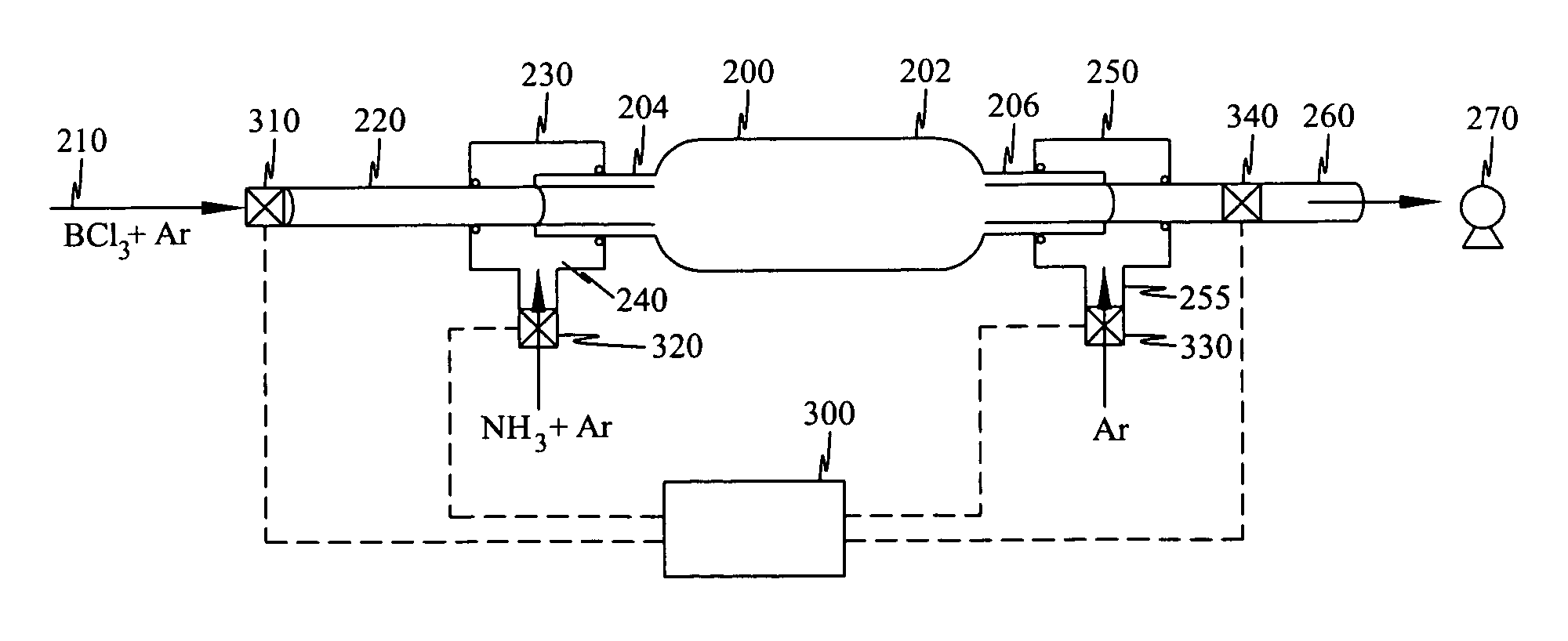
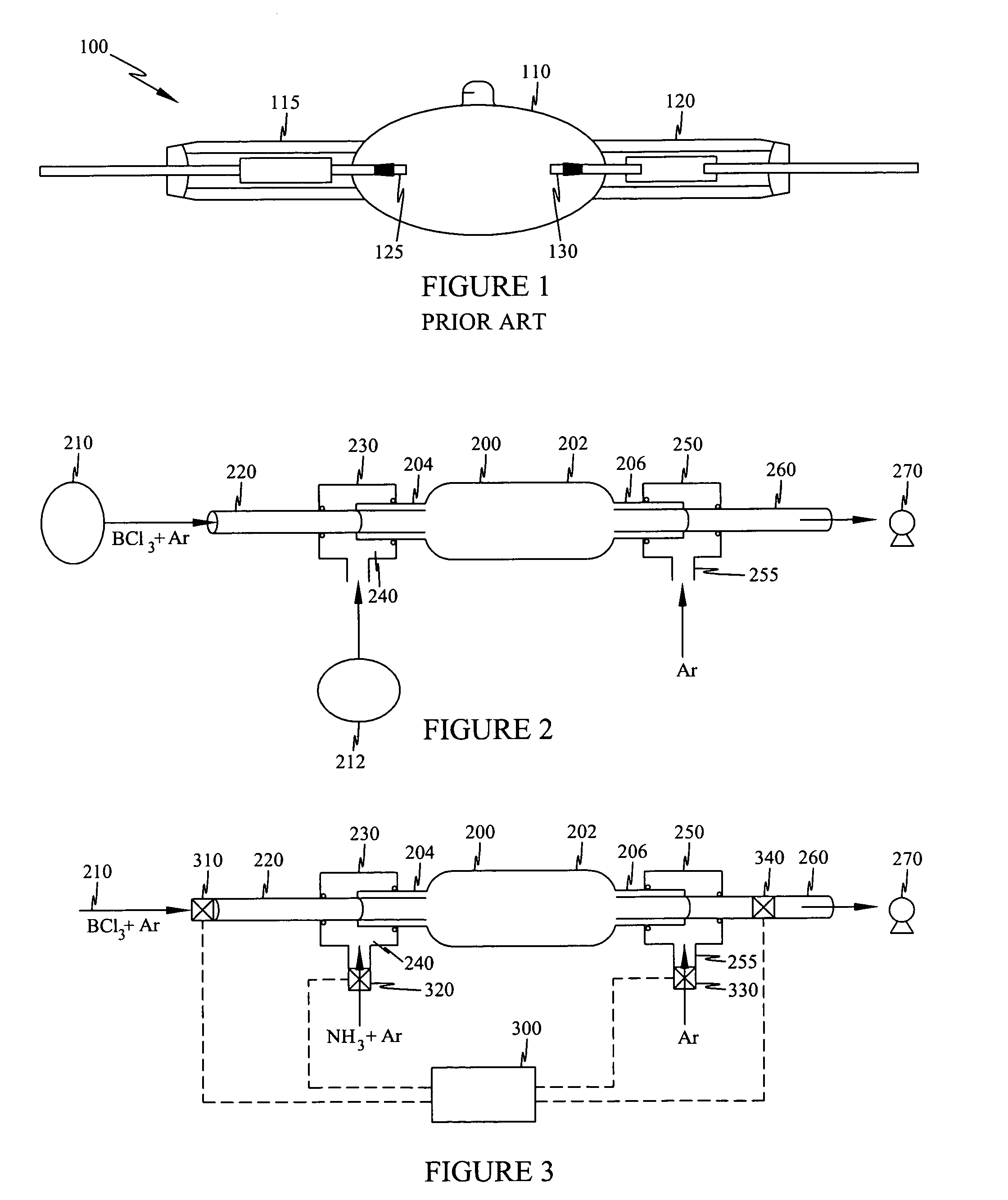
[0039]A series of experiments were conducted to optimize the timing sequence for a solenoid controlled batch reaction vapor deposit. In these experiments, the timing sequence can be summarized as follows:

[0040]T1: intake closed, exhaust open (evacuate the arc tube)

[0041]T2: intake open, exhaust closed (load reactants and inert gas into the arc tube)

[0042]T3: intake closed, exhaust closed (reaction time)

[0043]There was a 0.1 second delay between steps T1 and T2 to allow the exhaust valve to close. Table 1 summarizes the results of the experiments.

[0044]

TABLE 1Summary of experimentsTrialNH3BCl3T1T2T3NNo.ml / minml / minSecSecSecShotsComments192.02.00.50.10.5250Optically clear coating. UVabsorption spectrum characteristicof BN.212.05.00.50.10.5250Optically clear coating. UVabsorption spectrum characteristicof BN.222.00.70.50.10.5250Optically clear coating. UVabsorption spectrum characteristicof BN.232.00.80.50.10.5250Optically clear coating. UVabsorption spectrum characteristicof BN.241.00...


PUM

PropertyMeasurementUnit
Temperatureaaaaaaaaaa

Abstract

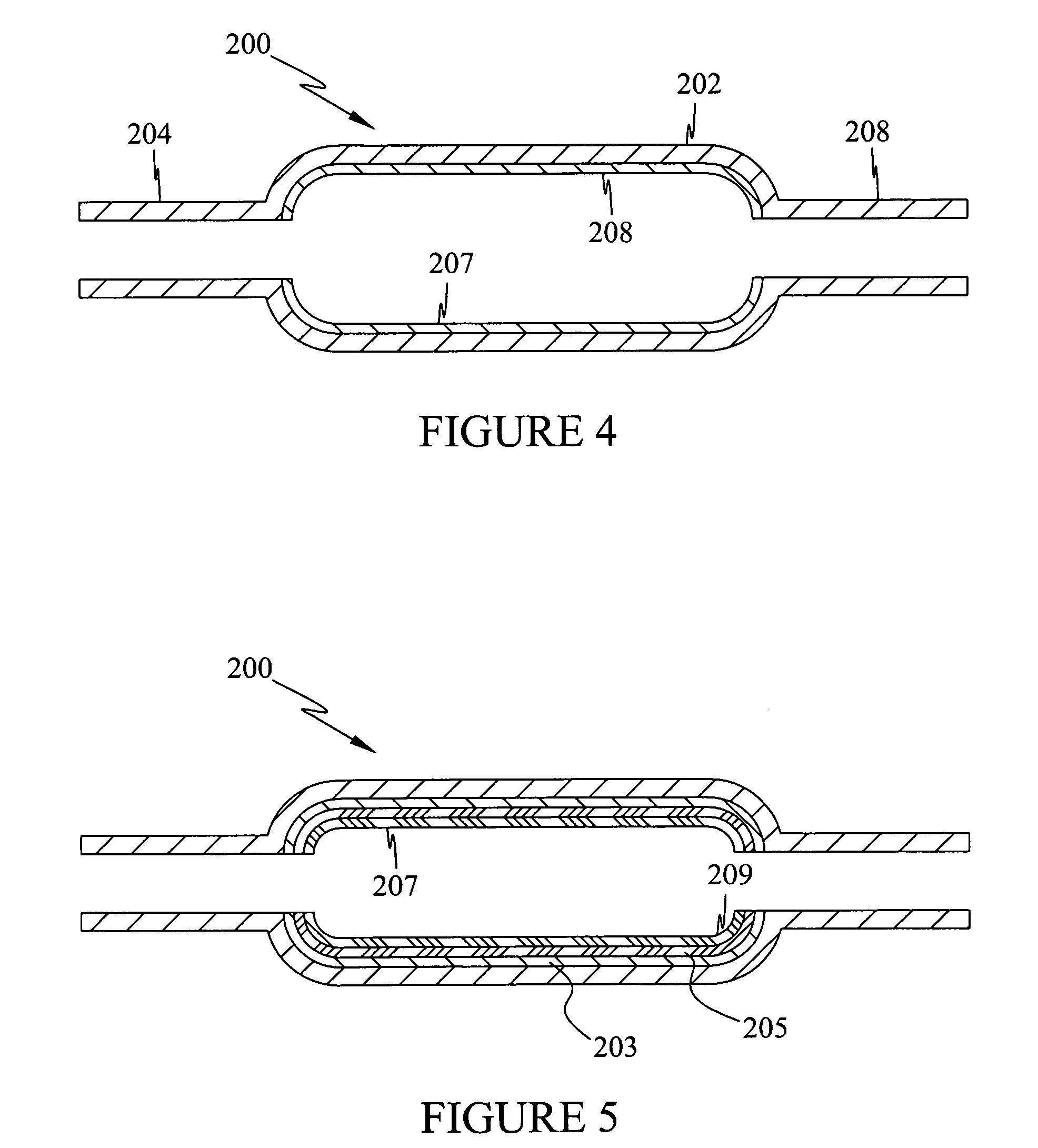
The present invention includes barrier coatings and methods for reducing or preventing chemical reaction between the discharge medium and arc tube wall material in discharge lamps. The barrier coatings comprise nitride layer exposed to the discharge medium formed from one or more of aluminum, boron, scandium, yttrium, or the lanthanides. In another aspect, the present invention includes methods of forming coatings on the inner wall of arc tubes by introducing two or more precursors into the arc tube chamber and pyrolitically reacting the precursors to form layers for the coating.

Description

RELATED APPLICATIONS[0001]This application claims the filing-date benefit of U.S. Provisional Patent Application Ser. No. 60 / 424,714 filed Nov. 8, 2002, and incorporates this application herein in its entirety.BACKGROUND OF THE INVENTION[0002]The present invention relates to discharge lamps having a light emitting plasma contained within an arc tube. More particularly, the present invention relates to such discharge lamps having a coating applied to the inner wall of the arc tube to reduce or prevent chemical reaction between the discharge medium and the arc tube wall material or loss of fill material through the arc tube wall.[0003]Discharge lamps such as mercury lamps, metal halide lamps, and high pressure sodium lamps include an arc tube forming a light emitting chamber containing the light emitting plasma. Typically the arc tubes are formed from a vitreous material such as fused silica and hard glass, or a ceramic material. The lamp fill material varies among the lamp types. For...

Claims


Application Information

Patent Timeline
IPC IPC(8): H01J61/35C23C16/04C23C16/34H01J1/62H01J9/00H01J9/20H05B
CPCC23C16/045H01J61/35H01J9/20C23C16/34H01J9/00
Inventor EMILSSON, TRYGGVIBRUMLEVE, TIMOTHY R.VARANASI, CHAKRAPANI V.
Owner ADVANCED LIGHTING TECH
Learn More