Display element

a technology of display elements and elements, applied in the field of display elements, can solve the problems of limited reading sites, user fatigue, and inability to read for a long time, and achieve the effects of preventing ion diffusion range overlap, and effective preventing ions from invading adjacent pixels

Inactive Publication Date: 2006-06-06
SONY CORP +1
View PDF7 Cites 14 Cited by
  • Summary
  • Abstract
  • Description
  • Claims
  • Application Information

AI Technical Summary

Benefits of technology

[0024]In the display element of the present invention, at least either of the electrodes is covered with the insulating material in an area exclusive of at least the pixel area, and the distance L between the effective electrode planes of the adjacent first electrodes is set twice or more as large as the distance between the second electrode surface and the effective electrode planes of the first electrode. The insulating material can effectively prevent the ions to be diffused and migrated from the respective first electrode towards the second electrode from otherwise diffusing into the areas around the pixel area on the second electrode side, or can effectively prevent ions from invading the adjacent pixels.
[0025]This consequently ensures thorough coloring of the desired pixels, prevents overlapping of the ion diffusion ranges among the pixels, avoids unnecessary coloring of the pixels not desired to be colored, and ensures high-quality and sharp display without causing crosstalk and blurring (mixing) of colors.
[0026]Moreover, the coloring and decoloring are effected based on electrochemical reduction and oxidation of the colorant material between the first electrodes and second electrodes, and the polymer electrolyte can promote these changes and assist the ion transfer. This is successful in proceeding the coloring and decoloring in a rapid and thorough manner even under a low energy supply, raising the contrast and coloring density (black density, for example), avoiding problems in color fading or the like after a long-term use by virtue of the memory effect, and allowing not only active matrix driving but also simple matrix driving.

Problems solved by technology

It has, however, been pointed out that these light-emitting-type displays would make the users heavily tired due to reasons related to human engineering when they are watched for a long duration of time, and that they are not suitable for reading for a long duration of time.
An additional disadvantage is that sites of reading are limited only at around places where computers with display devices are installed.
While recent dissemination of laptop computers made it possible to use some of them as mobile displays, they are still not suitable for reading for a long duration of time because they are intrinsically of light-emitting type and problems in power consumption remain unsolved.
This results in only a far poorer visibility as compared with that of printing on paper, is more causative of fatigue, and is far from ensuring comfortable reading for a long duration of time.
These methods, however, have drawbacks in that they can attain only a poor contrast because the light is undesirably absorbed by gaps between the particles, and this makes it impossible to achieve a practical write speed (within one second) unless drive voltage is raised to as high as 100 V or above.
The conventional displays based on electro-chemical reaction, however, could not adopt the simple matrix system due to their large energy consumption for the driving, and instead the active matrix system have inevitably been adopted.
This has consequently raised price of the display devices, so that there have been strong demands for the devices which can be driven based on the simple matrix system.

Method used


Image

  • Display element
  • Display element
  • Display element

Examples


example 1

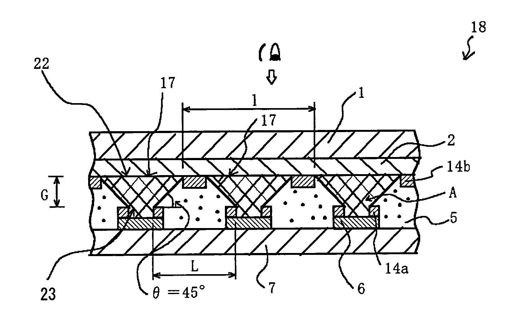
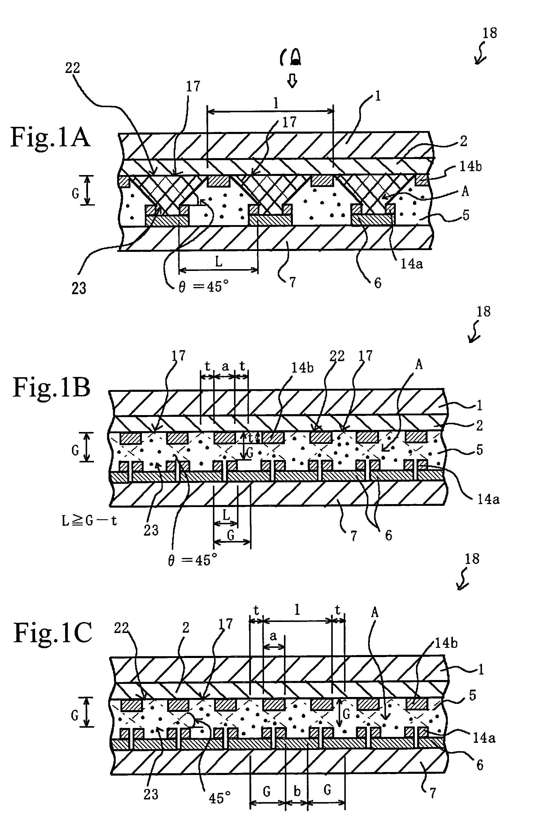
[0098]In the display element 18 of this example, as shown in FIGS. 1A to 1C, the insulating films 14b and 14a composed of SiO2 are disposed at the predetermined positions on both of the transparent pixel electrodes 2 and the opposing electrodes 6.

[0099]In the display element 18, the portions of the transparent pixel electrodes 2 covered with the insulating film 14b are not causative of colored display because donation and acceptance of electrons between the metal ions, which are the electrolyte, and the transparent pixel electrodes are prohibited in that portions, and so that electro-chemical deposition of the metal ions contained in the polymer solid electrolyte layer will never occur (the same will apply for the description below). The ion diffusion range A is thus restricted substantially within an area inside the insulating film 14b, and this allows the metal to deposit (or allows the coloring) only within the pixel portions 17.

[0100]Pattern of the insulating film 14b is designe...

example 2

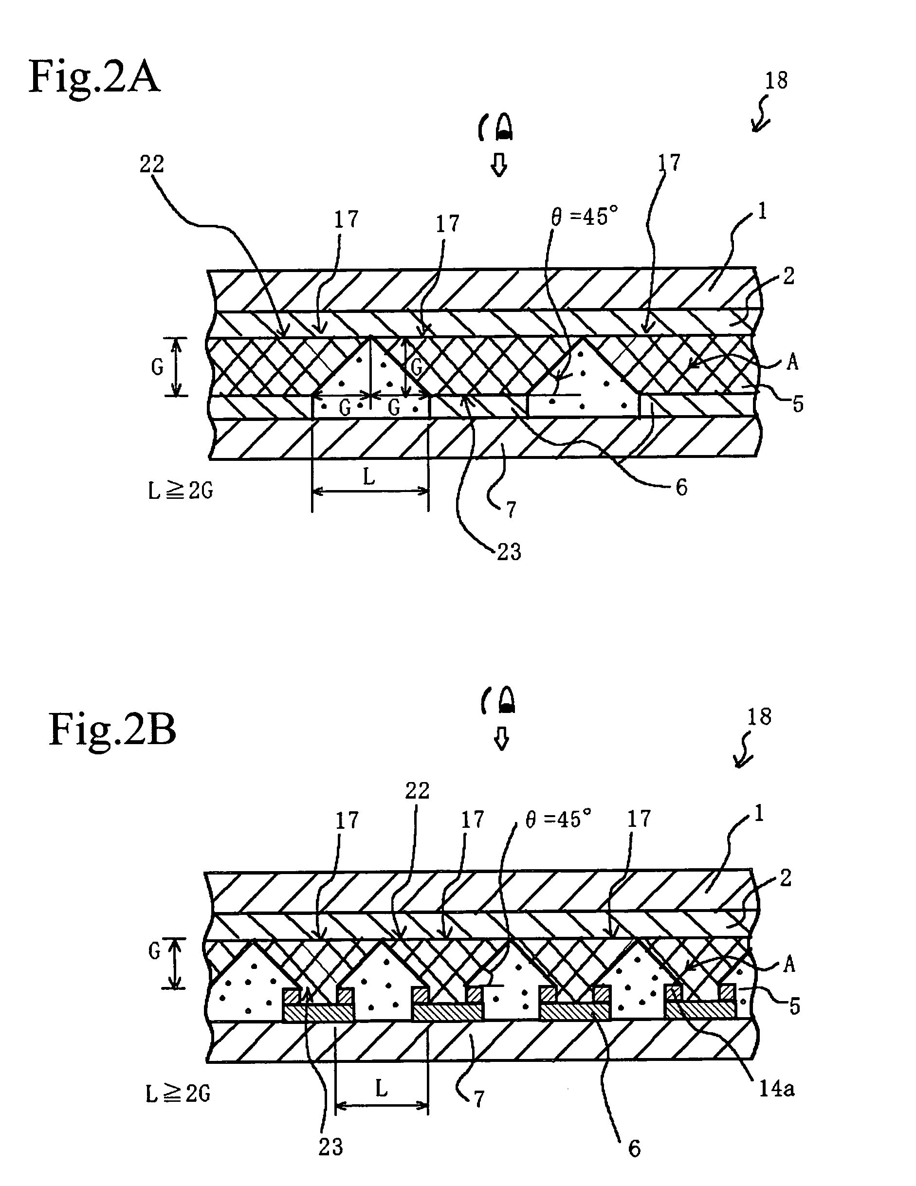
[0119]This embodiment represents the case where the insulating film 14b is not provided at all on the transparent pixel electrode 2, as shown in FIG. 2A, and instead the distance L between the effective electrode planes of the adjacent opposing electrodes 6 is widened enough so that the individual ion diffusion ranges on the adjacent opposing electrodes 6 do not overlap with each other to thereby suppress the crosstalk, etc.

[0120]That is, in order to avoid the overlapping of the ion diffusion ranges on the adjacent opposing electrodes 6 to thereby suppress the crosstalk, etc., the range of the distance L between the effective electrode planes of the adjacent opposing electrodes 6 is defined so as to satisfy the relation of:

L≧2G.

[0121]If the relation of L6 are too close with each other, and this causes the overlapping of the ion diffusion ranges and results in the crosstalk, etc.

[0122]In the next case where only the insulating film 14a is provided on the opposing electrodes 6 side, w...

example 3

[0125]In the next case where only the insulating film 14b is provided on the transparent pixel electrodes 2 side as shown in FIG. 3A, the opposing electrodes 6 in this display element 18 are arranged so that the ions can reach the entire area of the pixel portions 17 partitioned by the insulating film 14b formed on the transparent pixel electrodes 2 without causing waste, and this brings the pixel portions 17 into a status excellent in the display efficiency.

[0126]That is, for the case where the adjacent opposing electrodes 6 come close to with each other, the distance L between the effective electrode planes of the adjacent opposing electrodes 6 should satisfy the relation of:

L≧G.

This is successful in avoiding the crosstalk between the adjacent pixels as shown in FIGS. 7A and 7B, and also avoiding color blurring or mixing.

[0127]If the relation of L6 are too close with each other, so that it is no more possible for the insulating film 14b on the transparent pixel electrodes 2 side t...


PUM

PropertyMeasurementUnit
reflectivityaaaaaaaaaa
drive voltageaaaaaaaaaa
angleaaaaaaaaaa

Abstract

A display element not causative of crosstalk, ensures sharp display, and can be driven at a low energy is disclosed. In the display element (18), a polymer solid electrolyte layer (5) which contains a colorant material such as bismuth chloride or AgI, capable of causing deposition, dissolution or color change based on electrochemical reduction or oxidation, is disposed between transparent pixel electrodes (2) and opposing electrodes (6), and at least the transparent pixel electrodes (2) are covered with an insulating material (14b) in an area exclusive of at least pixel portions (17).

Description

BACKGROUND OF THE INVENTION[0001]The present invention relates to a display element using a display material capable of causing deposition, dissolution or color change based on, for example, electrochemical reduction or oxidation.[0002]With recent dissemination of network, there are increasing trends in distributing various documents in a form of so-called electronic document, instead of in a conventional form of printed matter. Also books and magazines are becoming more frequently distributed through electronic publishing.[0003]A conventional way for viewing these information is such as reading the information on cathode ray tubes (CRTs) or on liquid crystal displays (LCDs). It has, however, been pointed out that these light-emitting-type displays would make the users heavily tired due to reasons related to human engineering when they are watched for a long duration of time, and that they are not suitable for reading for a long duration of time. An additional disadvantage is that s...

Claims


Application Information

Patent Timeline
Patent Type & Authority Patents(United States)
IPC IPC(8): G02F1/15G02B5/22C09K9/00C09K9/02G02F1/153G09F9/30
CPCG02F1/1508G02F1/1533G02F2001/1536G02F1/15G02F1/153
Inventor SHINOZAKI, KENJIMITSUHASHI, HIROYUKI
Owner SONY CORP
Why Eureka
Try Eureka