
Degradable additive for viscoelastic surfactant based fluid systems

a technology of viscoelastic surfactant and additive, which is applied in the direction of fluid removal, well accessories, chemistry apparatus and processes, etc., can solve the problems of undesirable or unacceptable continued presence of filter cake, low viscosity of viscoelastic surfactant system, and high permeability formations that are often poorly consolidated, so as to reduce the viscosity of the viscoelastic surfactant system

Inactive Publication Date: 2007-05-22
SCHLUMBERGER TECH CORP
View PDF50 Cites 124 Cited by
  • Summary
  • Abstract
  • Description
  • Claims
  • Application Information

AI Technical Summary

Benefits of technology

The patent describes a method for treating a subterranean formation by injecting a fluid containing a viscoelastic surfactant system, a pH control agent, and a solid material precursor of an acid breaker. The solid material particles enter the pores of the formation and the pH control agent neutralizes any acid present in the solid material before and during the injection. The solid material can be selected from substituted and unsubstitbed lactide, glycolide, polylactic acid, polyglycolic acid, copolymers of these acids, and mixtures of these materials. The method can be used to break the viscous fluid in the formation and improve the flow of fluid through the formation.

Problems solved by technology

Such applications are those in which, without a filter cake, fluid would leak off into porous rock at an undesirable rate during a well treatment.
Typically, after these treatments have been completed the continued presence of the filter cake is undesirable or unacceptable.
High permeability formations are frequently poorly consolidated, so that sand control is needed.
This can sometimes be accomplished in the wellbore but normally cannot be done in a proppant or gravel pack.
However, these methods require fluid flow and often result in slow or incomplete filter cake removal.
Sometimes a breaker can be incorporated in the filter cake but these must normally be delayed (for example by esterification or encapsulation) and they are often expensive and / or difficult to place and / or difficult to trigger.
This technique, sometimes called a “water-frac” involves using extremely low polymer concentrations, so low that they cannot be effectively crosslinked, throughout the job.
This alternative has a major drawback: since there is inadequate viscosity to carry much proppant, high pump rates must be used and only very small concentrations (pounds mass proppant added per gallon of fluid), called “PPA”, of proppant can be used.
VES's are popular because they leave very clean proppant or gravel packs, but they don't form a filter cake by themselves.
VES fluids without fluid loss additives do not form filter cakes as a result of leak-off.
Fluid loss control may not always be optimal with VES systems, especially in higher permeability formations.
On the other hand, polymers have two major deficiencies: a) the filter cake, if left in place, can impede subsequent flow of hydrocarbons into the fracture and then into the wellbore, and b) polymer or crosslinked polymer will be left in the fracture itself, impeding or cutting off flow, either by physically blocking the flow path through the proppant pack or by leaving a high viscosity fluid in the fracture.
They are easier to use because they require fewer components and less surface equipment, but they may be less efficient than polymers, depending upon the formation permeability and the specific VES system.
Disturbance of the charge balance, due for instance to removing the water, changing the pH or adding salt or water-miscible organic solvent, causes the colloidal particles to aggregate, resulting in the formation of a gel.
Further, degradation products of such materials have been shown to cause delayed breaking of polymer-viscosified fracturing fluids.
Since VES fluid systems cause negligible damage, it would be desirable to use a fluid loss additive that is compatible with the VES system and also causes negligible damage.
It would be desirable to use polyglycolic acid and similar materials as a fluid loss additive for VES fluid systems, but this creates a problem because these materials often contain small amounts of acid as commercially obtained and furthermore these materials typically start to hydrolyze to form acids as they are being used.
Therefore, simply adding the PGA or similar material to the VES fluid system would not be an acceptable solution to the problem.
Inherently present monomeric acid or early dissolution of some of the PGA or similar material would deleteriously affect the viscosity of the system.

Method used


Image

  • Degradable additive for viscoelastic surfactant based fluid systems
  • Degradable additive for viscoelastic surfactant based fluid systems
  • Degradable additive for viscoelastic surfactant based fluid systems

Examples


example 1

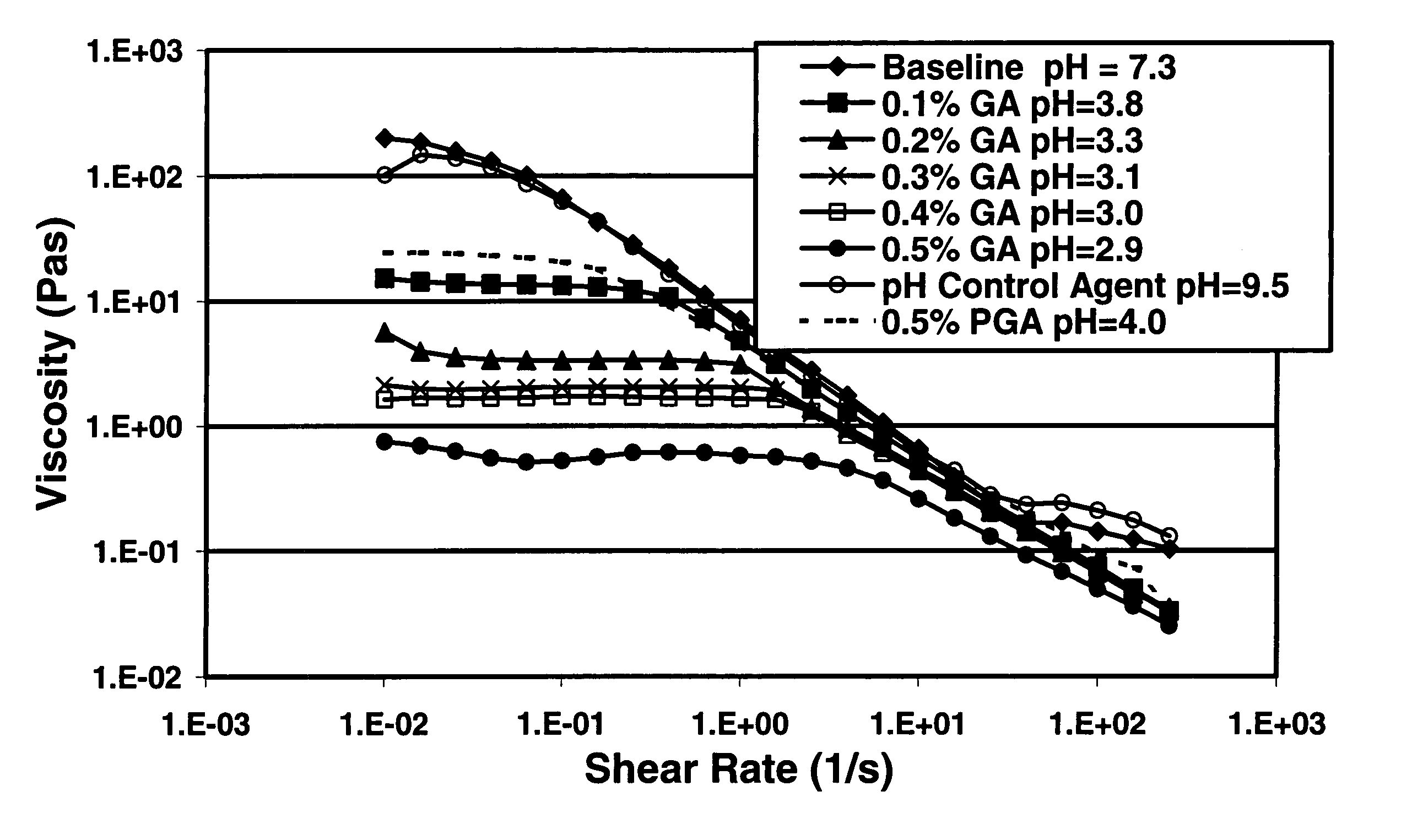
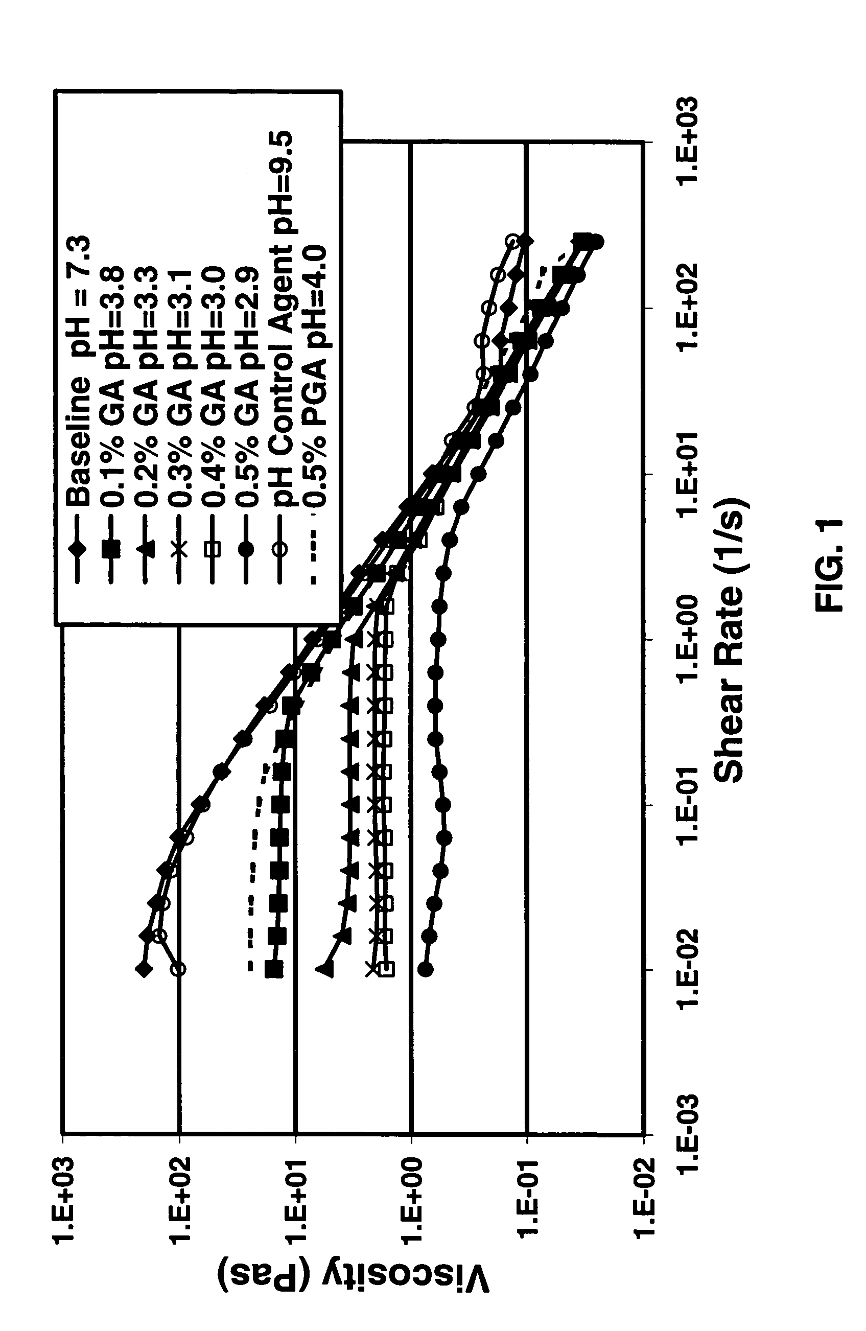
[0057]FIG. 1 shows measurements of the viscosity of one example of a VES fluid system with different amounts of glycolic acid (GA) dissolved in the fluid. Measurements were conducted at 66° C. (150° F.). The pH control agent used in the experiments shown in FIG. 1 was sodium sesquicarbonate, which was used at a concentration of 30 pounds per thousand gallons (3.6 g / L) in all experiments. The VES fluid system was made with 6% of a material called BET-E-40 obtained from Rhodia, Inc. Cranbury, N.J., U.S.A.; it contains a betaine VES surfactant having an erucic acid amide group (including a C21H41 alkene tail group) and is about 40% active ingredient, with the remainder being substantially water, sodium chloride, and isopropanol. (Before use, about 1% of DAXAD 17, a low molecular weight sodium polynaphthalene sulfonate available from Hampshire Chemical Corporation, Nashua, N.H., USA, was added to the as-received betaine surfactant BET-E-40.) This experiment showed the results that would...

example 2

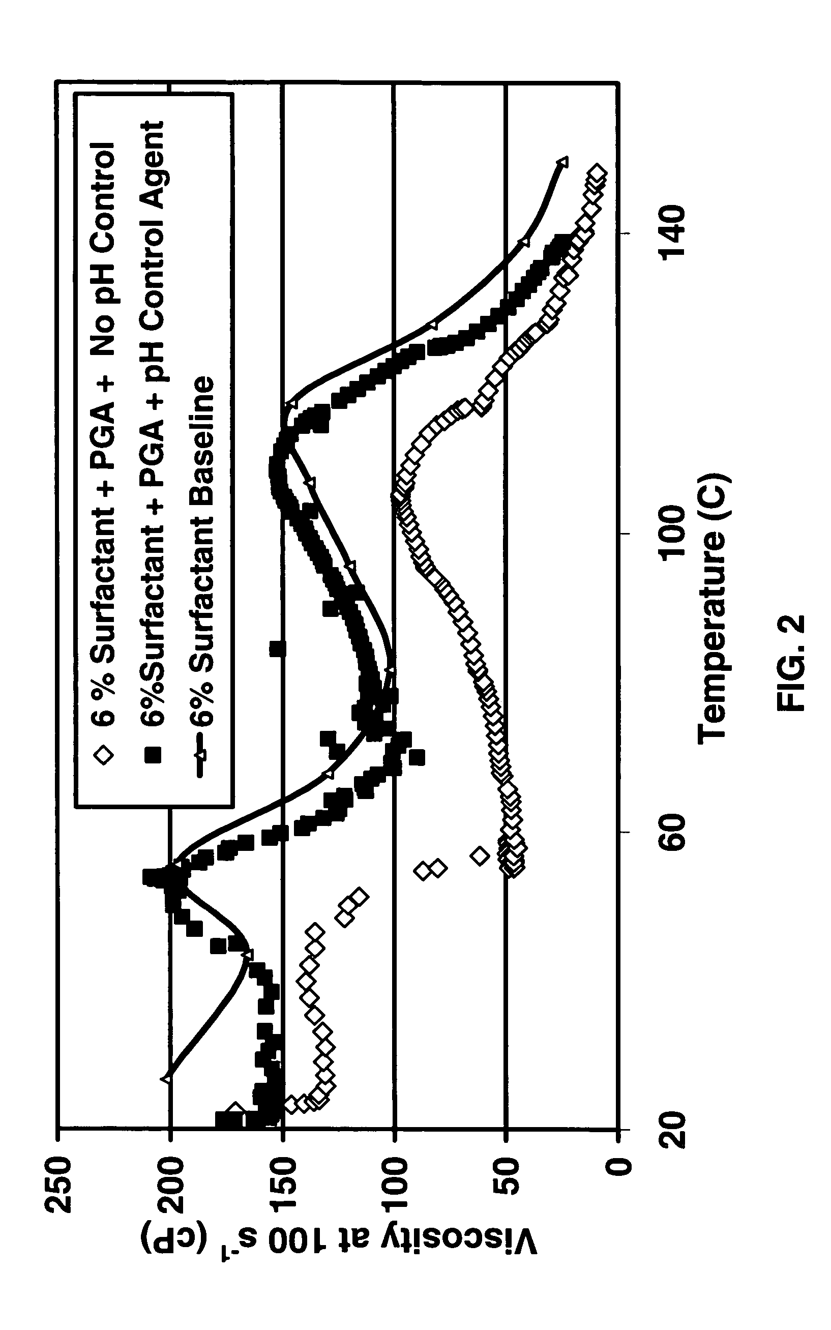
[0059]FIG. 2 shows the viscosity of the same 6% surfactant fluid system as the baseline system of the experiments shown in FIG. 1, determined with a Fann 50 Viscometer over a range of temperatures, with PGA added, with and without the pH 9.5 pH control agent. Without the pH control agent in place, the viscosity of the fluid was substantially reduced; therefore this material would have been unsatisfactory as a viscous oilfield treatment fluid, for example as a fracturing or gravel packing carrier fluid. With the pH control agent present, the viscosity of the fluid system containing the PGA was essentially identical to the viscosity of the baseline system. The total duration of each of these experiments was about 3 hours. At the end of the run with the pH control agent it can be seen that the viscosity dropped below the baseline, suggesting that the hydrolysis of the PGA at the higher temperature was starting to break the fluid when the temperature was above about 121° C. (250° F.). (...

example 3

[0061]Prior to fracturing the lower zone of a well in the Gulf of Mexico, from a mini-fall-off measurement (a simple test in which a viscous fluid is injected, a fracture is created, and the pressure fall-off is observed) it was estimated that the permeability of the sandstone zone that was 16 feet high, was 2.45 mD. The formation temperature was 195° F. (91° C.) and the volume injected was 2329 US gallons (8.82 m3). The step rate fall off measurement without a solid acid and pH control agent in a VES gave a measured fluid loss coefficient, Ct, of 0.072 ft / min1 / 2. When a solid acid and pH control agent were then placed (4768 US gallons (18.05 m3) of a slurry containing 5 volume percent of BET-E-40 (containing about 1% sodium polynaphthalene sulfonate), 4.8 g / L (40 ppt) of PGA beads about 90% smaller than 20 microns, 4 weight percent KCl, and 4.2 g / L (35 ppt) sodium sesquicarbonate) and a DataFRAC was performed, the measured Ct was reduced in half to 0.035 ft / min ½. (A DataFRAC is a ...


PUM

PropertyMeasurementUnit
diameteraaaaaaaaaa
diameteraaaaaaaaaa
concentrationaaaaaaaaaa

Abstract

A method is given for treating a subterranean formation penetrated by a wellbore with a viscosified fluid. The fluid contains a solid hydrolysable polyacid that upon dissolution and hydrolysis releases an acid that is a breaker for the viscosifying system. Suitable solid hydrolysable polyacids include polylactic acid and polyglycolic acid. The fluid also contains a pH control agent, present in an amount sufficient to neutralize any acid present in the solid hydrolysable polyacid before the injection and to neutralize any acid generated by the solid hydrolysable polyacid during the injection, so that the acid breaker is not available to break the fluid during the injection. In one embodiment the viscosifier is a viscoelastic surfactant fluid system and the solid hydrolysable polyacid is of a size selected to be a fluid loss additive, for example in fracturing or gravel packing. In another embodiment, the solid hydrolysable polyacid is used in particles sufficiently small that they enter the pores of the formation. In either case, the viscosifier is broken after the solid releases more acid than can be neutralized by the pH control agent.

Description

CROSS-REFERENCE TO RELATED APPLICATION[0001]This application claims the benefit of U.S. Provisional Patent Application Ser. No. 60 / 584,995, filed on Jul. 2, 2004, and is a CIP of and also claims the benefit of U.S. patent application Ser. No. 10 / 707,022, filed Nov. 14, 2003, now U.S. Pat. No. 7,066,260, which is a CIP of U.S. patent application Ser. No. 10 / 227,690 filed on Aug. 26, 2002, now U.S. Pat. No. 6,938,693.BACKGROUND OF THE INVENTION[0002]This invention relates to recovery of oil and gas from wells, more particularly to hydraulic fracturing and gravel packing, and most particularly to decreasing fluid loss and damage due to fluid loss additives when using viscoelastic surfactant fluid systems as carrier fluids.[0003]There are many oilfield applications in which filter cakes are needed in the wellbore, in the near-wellbore region or in one or more strata of the formation. Such applications are those in which, without a filter cake, fluid would leak off into porous rock at an...

Claims


Application Information

Patent Timeline
Patent Type & Authority Patents(United States)
IPC IPC(8): E21B43/04E21B43/22E21B43/267C09K8/68C09K8/70
CPCC09K8/506C09K8/62C09K8/68C09K8/70C09K8/72C09K8/74C09K2208/26C09K2208/30Y10S507/902
Inventor SULLIVAN, PHILIP F.BROWN, J ERNESTLEE, JESSE C.SALAMAT, GOLCHEHREH
Owner SCHLUMBERGER TECH CORP
Learn More