Sliding-window multi-carrier frequency division multiplexing system

a multi-carrier, sliding window technology, applied in multiplex communication, orthogonal multiplex, pulse technique, etc., can solve the problems of carrier frequency shift, loss of signal path, hostile transmission environment of desired communication signal, etc., to achieve the effect of improving performan

Inactive Publication Date: 2006-06-06
THOMSON LICENSING SA +2
View PDF15 Cites 18 Cited by
  • Summary
  • Abstract
  • Description
  • Claims
  • Application Information

AI Technical Summary

Benefits of technology

[0028]The present invention solves these and other problems by providing a multi-channel receiver that uses sliding-window processing of received signals to provide improved performance over block-based OFDM systems. The received signals are processed according to a transform that is based on a sliding window. In one embodiment, the sliding window transform uses a set of basis functions. The width of the sliding window is typically relatively shorter than the symbol time, however, the width of the sliding window can be the same as the symbol time even though the delay spread from sub-channel-to-sub-channel is significant. In one embodiment, the basis function length is not significantly shorter than the symbol time even in the face of large channel-to-channel delay spreads. The sliding-window system provides relatively more local orthogonality (that is, orthogonality between adjacent or nearby sub-carriers) and relatively less global orthogonality (that is, orthogonality between all sub-carriers) than a conventional block-based OFDM receiver.

Problems solved by technology

Many communication channels, such as, for example, Radio Frequency (RF) channels, power line channels, and the like, often present a hostile transmission environment for the desired communication signals.
These hostile channels can produce a variety of interference mechanisms, including multipath interference, amplitude fading, phase shifts, noise, etc.
Moreover, the channel typically adds noise to the signal and, in some environments, can cause a shift in the carrier frequency.
Attenuation can be caused by the transmission path length, obstructions in the signal path, loss in the signal path, and multipath effects.
As a result, the channel spectral response is typically not flat or uniform.
This can cause deep nulls in the received signal power due to destructive interference.
For narrow-band channels, if the null in the frequency response occurs at the transmission frequency, then the entire signal can be lost.
For example, by transmitting a wide-bandwidth signal (e.g. spread-spectrum), any dips in the spectrum only result in a small loss of signal power.
This will result in only some of the carriers being lost, rather than the entire signal.
In a digital system, the delay spread can lead to inter-symbol interference.
This can cause significant errors in high bit rate systems, especially when using time division multiplexing (TDMA).
As the transmitted bit rate is increased, the amount of inter-symbol interference typically also increases.
Unfortunately, the spectral efficiency of this type of system is relatively low and therefore unsuitable for systems where high spectral efficiency is desired.
With FDM there remains the problem of fading.
However, the minimum required bandwidth for speech is only 3 kHz.
In a typical system up to 50% of the total spectrum is wasted due to the extra spacing between channels.
This problem becomes worse as the channel bandwidth becomes narrower and the frequency band increases.
For a large number of sub-channels, the arrays of sinusoidal generators, modulators, and demodulators can become unreasonably expensive and complex.
This results in the signal having a high tolerance to multipath delay spread, as the delay spread must be very long to cause significant inter-symbol interference.
If the delay spread is longer than the guard interval, then they begin to cause inter-symbol interference.
Inter-symbol interference occurs when spectrum of a symbol on one sub-channel interferes with the spectrum of a subsequent or prior symbol on the same sub-channel.
Inter-carrier interference occurs when the spectrum of a symbol on one channel interferes with the spectrum of a symbol on a different channel
Unfortunately, the need for a guard period reduces the symbol rate that can be transmitted on the channel.
This means that the guard period on a conventional OFDM system can significantly reduce the overall system data rate.
The length of the guard band is adversely affected by the delay spread across the channels, because the guard band must be long enough to deal with a worst-case delay-spread across all of the channels.
In some environments, especially where the channel-to-channel delay spread is very large, the length of the guard band can become prohibitively long and can significantly reduce throughput.

Method used


Image

  • Sliding-window multi-carrier frequency division multiplexing system
  • Sliding-window multi-carrier frequency division multiplexing system
  • Sliding-window multi-carrier frequency division multiplexing system

Examples


Embodiment Construction

[0073]For the sake of clarity in the following disclosure, a distinction is made between sub-carriers and sub-channels when dealing with sinusoidal basis functions. Generally, a sub-channel is a frequency bandwidth allocated for the transfer of the modulated signals. The carrier frequency is usually the carrier frequency of the sinusoidal signal used to modulate a baseband signal into the bandwidth of the sub-channel. The sub-carrier is the sinusoidal signal.

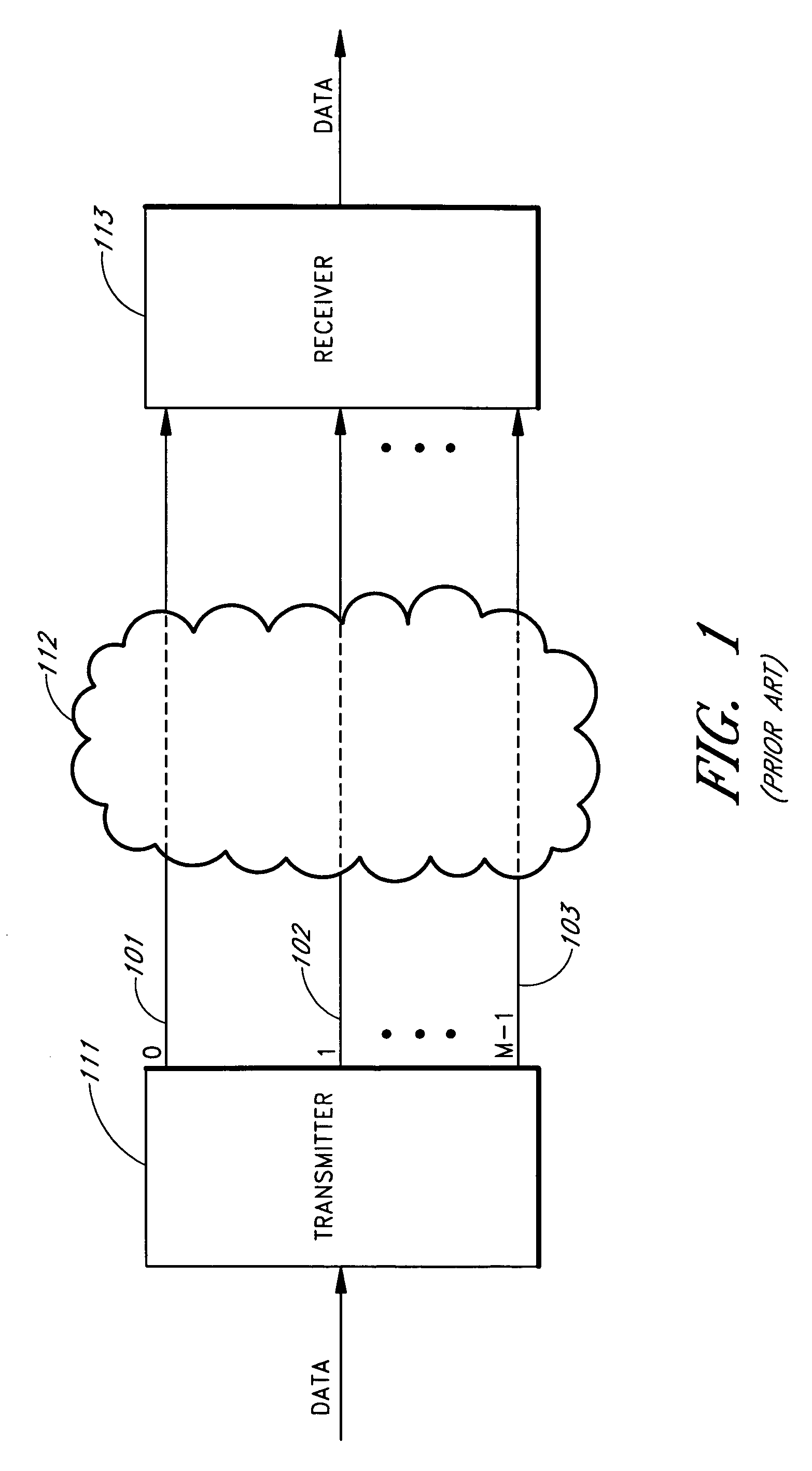
[0074]FIG. 1 is a block diagram showing a multi-channel medium 112 connecting a multi-channel transmitter 111 to a multi-channel receiver 113. The multi-channel medium 112 is configured to provide m separate data channels 101–103 shown as a first channel 101, a second channel 102, and an M-th channel 103. The multi-channel transmitter 111 provides a separate data output to each channel 101–103 and each of the multi-channels 101–103 is provided to a separate data input of the multi-channel receiver 113. In one embodiment, the mul...


PUM


Abstract

A sliding-window multi-carrier communication system is described, wherein the carriers are orthogonal in a local sense, but not necessarily in a global sense. In one embodiment, the system allows a reduction of the length of the basis function time as compared to conventional OFDM systems. In some circumstances, the symbol time can be reduced almost to the basis function length even though the delay spread from channel-to-channel is significant. In one embodiment, a discrete Fourier transform DFT is used in the sliding-window receiver. In one embodiment, the DFT produces M outputs (one output for each of M channels) for each time-domain input. In one embodiment, the DFT produces outputs for M channels from N samples, where N is a basis function length. In one embodiment, the sliding-window receiver provides an adjustable basis-function length. In one embodiment, the basis-function length can be separately selected for each channel. In one embodiment, the sliding-window receiver provides independent equalization for each channel by extracting equalization information from a packet header.

Description

REFERENCE TO RELATED APPLICATION[0001]The present application claims priority benefit of U.S. Provisional Application No. 60 / 211,934, filed Jun. 16, 2000, titled “CONTINUOUS-TIME ORTHOGONAL FREQUENCY DIVISION MULTIPLEXING,” the entire contents of which is hereby incorporated by reference.BACKGROUND OF THE INVENTION[0002]1. Field of the Invention[0003]The invention relates to communication systems that use multiple carriers to improve the bandwidth efficiency of the communication systems, where the carriers are locally orthogonal (but not necessarily globally orthogonal) according to a desired transform.[0004]2. Description of the Related Art[0005]Many communication channels, such as, for example, Radio Frequency (RF) channels, power line channels, and the like, often present a hostile transmission environment for the desired communication signals. These hostile channels can produce a variety of interference mechanisms, including multipath interference, amplitude fading, phase shifts...

Claims


Application Information

Patent Timeline
Patent Type & Authority Patents(United States)
IPC IPC(8): H04J3/00H04L27/144H04L27/26
CPCH04L27/2647H04L27/2602H04L27/26035
Inventor SMART, KEVIN J.STODDARD, TRENTON D.SHETTY, SACHINDEV
Owner THOMSON LICENSING SA
Why Eureka
Try Eureka